
Device for continuous filtration of material blends
a technology of material blends and filters, applied in the direction of moving filter elements, filtration separation, separation processes, etc., can solve the problems of residues being transported to the two outlet openings for a relatively long time, clogging of filter openings, and affecting the filtration body, so as to improve the stability of the device, reduce the wear and tear, and reduce the abrasive wear of the filter
- Summary
- Abstract
- Description
- Claims
- Application Information
AI Technical Summary
Benefits of technology
Problems solved by technology
Method used
Image

Examples
Embodiment Construction
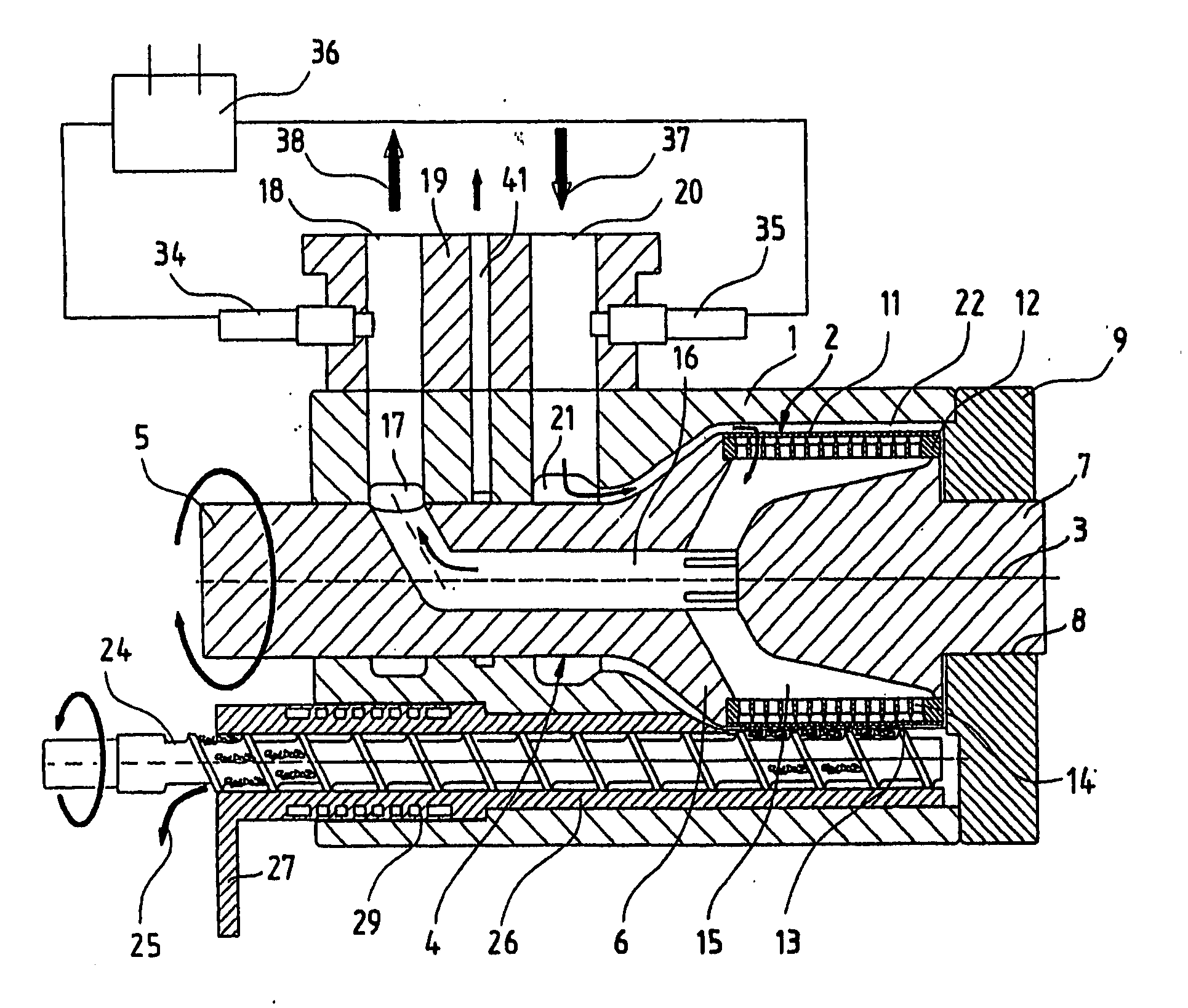
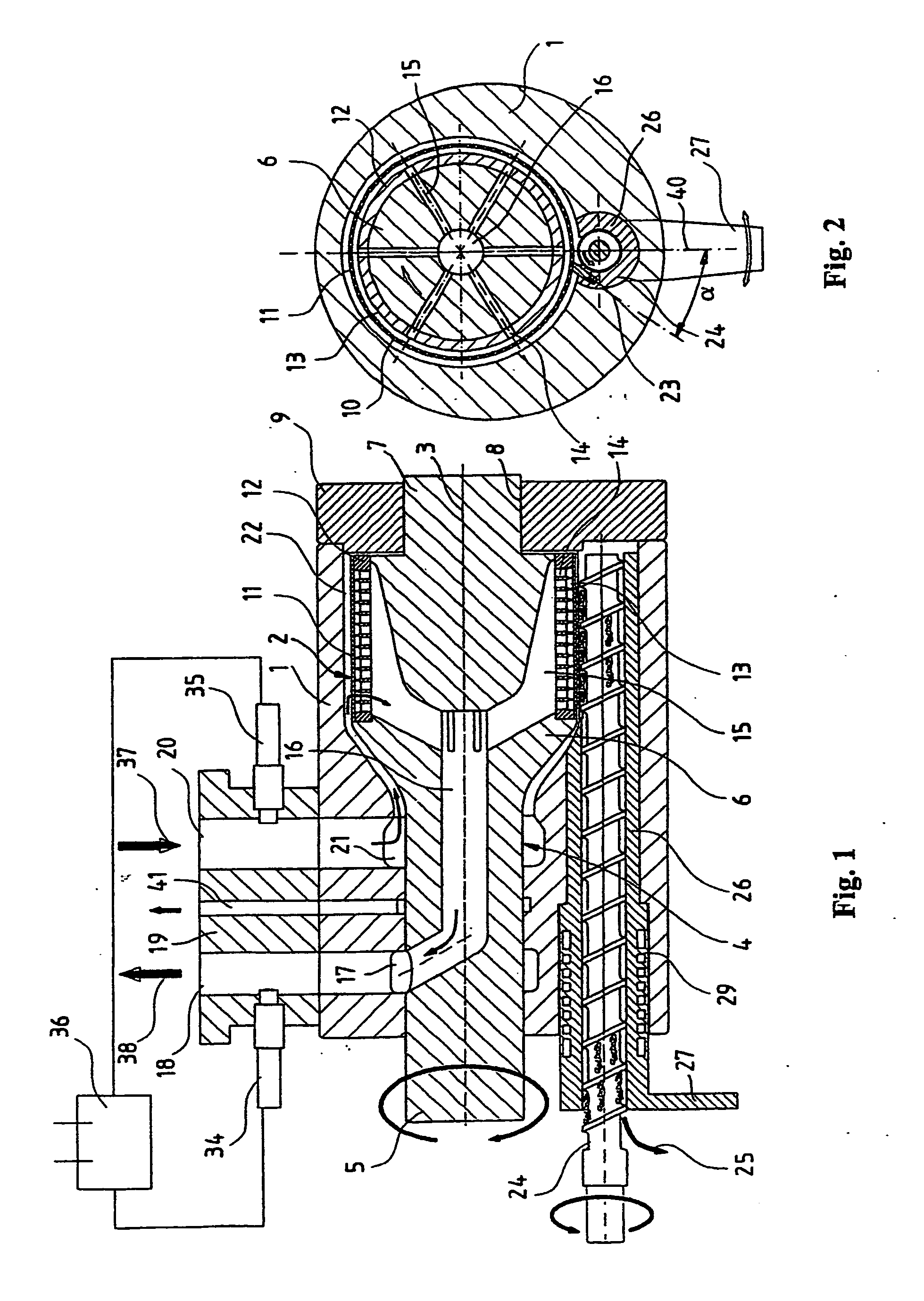
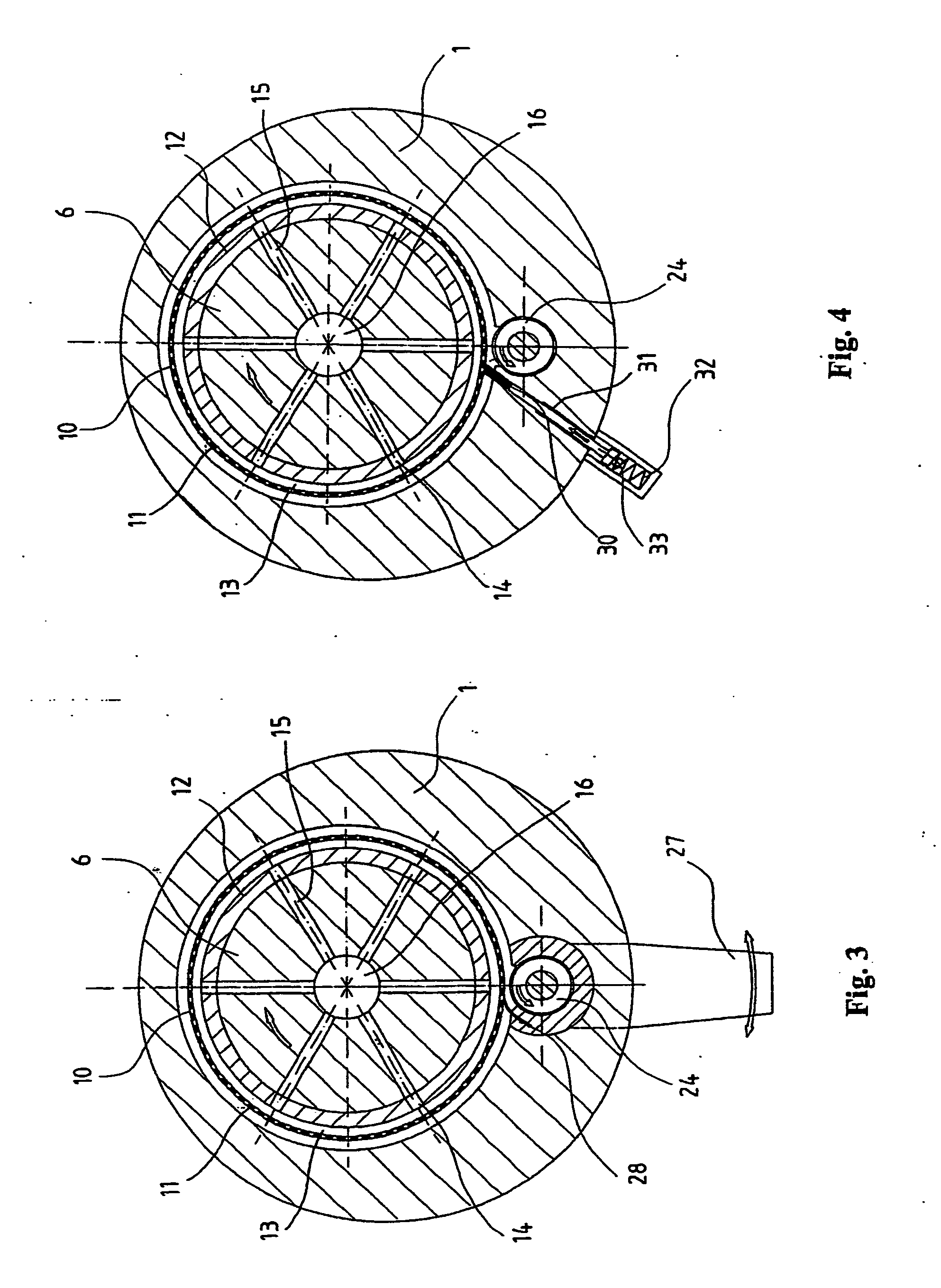
[0020] The separating device for filtering contaminated plastic melts diagrammatically shown in FIG. 1 comprises a housing 1 in which a melt filtration unit 2 in the shape of a hollow cylinder is disposed so as to be able to pivot about the axis of rotation 3. The melt filtration unit 2 is mounted on a motor-driven rotary-drive carrier shaft 4. This carrier shaft comprises a relatively slim drive element 5 that is disposed inside housing 1, a wider bearing element 6 for melt filtration unit 2, and a slimmer journal 7 which is pivoted in a suitable boring 8 of a bearing cap 9 that is attached to housing 1.
[0021] The melt filtration unit 2, which is shown enlarged in FIG. 5, comprises a filter tube 11 which has a plurality of radial thru openings 10 and a hollow cylindrical supporting body 12 which is form-fittingly connected to the carrier shaft 4 and onto which filter tube 11 is shrink-fitted. The strainer-like filter tube 11 can be fashioned, e.g., from sheet steel with thru openi...
PUM
| Property | Measurement | Unit |
|---|---|---|
| angle of pitch | aaaaa | aaaaa |
| oblique angle | aaaaa | aaaaa |
| angle of pitch | aaaaa | aaaaa |
Abstract
Description
Claims
Application Information