
Method of repairing a workpiece

a workpiece and workpiece technology, applied in the field of workpiece repair, can solve the problems of minor surface blemishes, scratches, and drill starts, and achieve the effects of reducing fatigue life, removing less material, and removing less workpieces

Inactive Publication Date: 2005-07-28
THE BOEING CO
View PDF7 Cites 14 Cited by
  • Summary
  • Abstract
  • Description
  • Claims
  • Application Information

AI Technical Summary

Benefits of technology

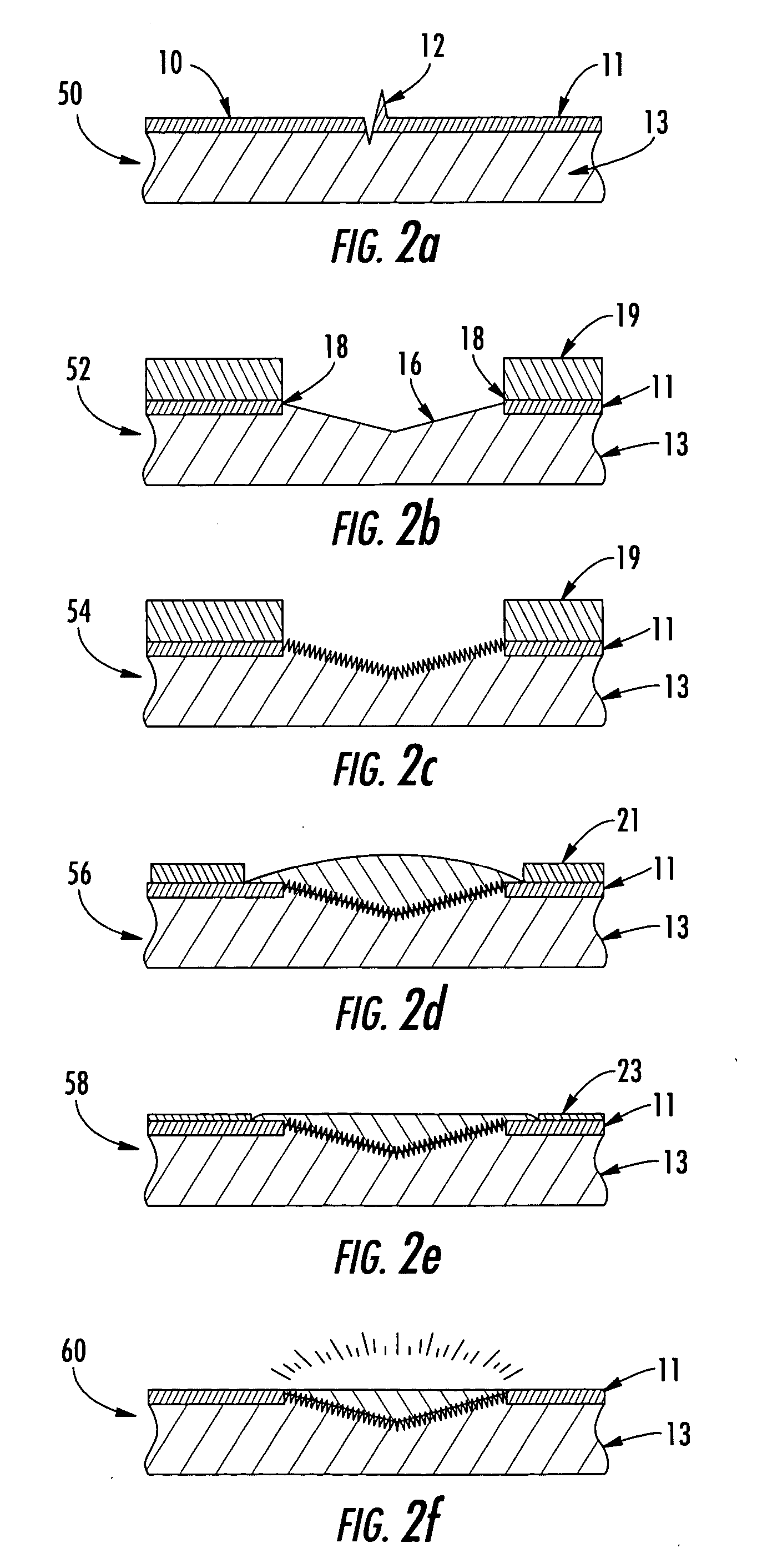
[0013] The method could also comprise additional steps. For example, the method could comprise blasting the portion of the workpiece that has been routed using grit to remove foreign particles prior to flame spraying. The grit blasting improves the adhesion of the flame sprayed material, as well as develops compressive residual stresses within the workpiece. The method could also comprise sanding the portion of the workpiece that has been flame sprayed. In addition, the method could include polishing the portion of the workpiece that has been flame sprayed following sanding.
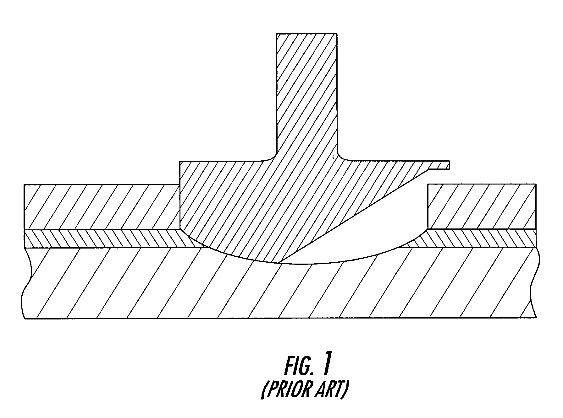
[0016] The present invention provides a method capable of removing less of the workpiece proximal to the defect than prior methods when preparing the workpiece for flame spraying. The current method includes a router bit having a profile that produces a cut in the workpiece that has a sidewall extending substantially perpendicular to the surface of the workpiece being repaired, as well as a conical bottom surface, such that the routed portion has sharp edges defined between the sidewall and the conical bottom surface. Previous methods were generally premised on the belief that sharp edges produced stress concentrations that would decrease fatigue life. In contrast to conventional wisdom, however, the repair method of the present invention is acceptable in terms of fatigue life even though the portion of the workpiece that is routed does not have a smooth transition. Therefore, the diameter of the router bit can be more closely matched to the defect being removed.
[0017] The design of the router bit used with the method of the present invention may remove less material than did prior cutters due to its non-rounded profile and shallow relief angle. The router bit includes multiple cutting edges that improve the stability and control of the router bit during routing. The router bit is also easier to control in terms of depth and location given that the router bit may be plunged into the workpiece while routing, as opposed to the sweeping motion in which prior router bits were moved. Thus, the router bit may be used to repair areas of the workpiece that are near fasteners or other hard to reach areas since a rounded blendout is not required. The plunging action of the router bit also enables the router bit to quickly remove material, which reduces the amount of time needed to make the repair.
[0018] The micro-stop countersink apparatus employed by at least some embodiments of the present invention allows the depth of the router bit to be closely controlled, which also permits the router bit to be used near fasteners and in very thin sheet metal. The micro-stop countersink apparatus also effectively controls the depth to which the router bit is plunged into the workpiece at predetermined increments. Thus, the router bit is prevented from penetrating below the workpiece to damage any underlying materials. The micro-stop countersink apparatus also improves the repeatability and visibility of the user when preparing the workpiece for flame spraying.

Problems solved by technology

With respect to an aircraft, for example, defects may result from drill starts, scratches, and minor surface blemishes caused by handling damage.
Drill starts are defects in the surface of a material that are formed when a mechanic drilling a hole into the material realizes that the hole location is off, but still accidentally touches the bit of the drill on the surface to make a small hole.
In addition, handling damage during manufacturing and maintenance as well as runway debris may also cause defects in the aircraft skin.
As such, sharp edges created by the router bit within the aircraft skin were undesirable because of the potential for stress concentrations (See FIG. 1).
Additionally, the router bit used to cut the workpiece is generally of a large diameter having a single cutting edge, such that routing around edges or fastener holes is difficult due to decreased visibility and stability of the router bit.

Method used


Image

  • Method of repairing a workpiece
  • Method of repairing a workpiece
  • Method of repairing a workpiece

Examples


Embodiment Construction

[0029] The present invention now will be described more fully hereinafter with reference to the accompanying drawings, in which some, but not all embodiments of the invention are shown. Indeed, this invention may be embodied in many different forms and should not be construed as limited to the embodiments set forth herein; rather, these embodiments are provided so that this disclosure will be thorough and complete, and will fully convey the scope of the invention to those skilled in the art. Like numbers refer to like elements throughout.

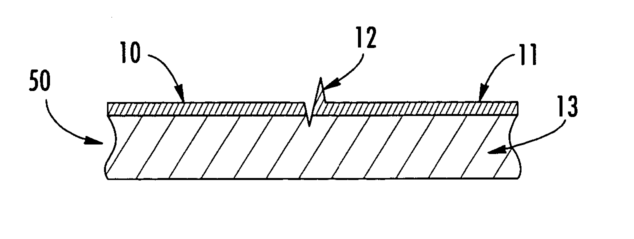
[0030] Referring now to the drawings and, in particular, to FIG. 2a, there is shown a workpiece 10 having a layer of sheet material 11 on the surface and adjacent to a layer of base material 13 underlying the layer of sheet material. The term workpiece 10 may include any number of materials, metallic or nonmetallic. For example, the top layer of sheet material 11 may be an aircraft skin, and more specifically, aluminum skin clad. However, the metho...


PUM

PropertyMeasurementUnit
relief angleaaaaaaaaaa
interior angleaaaaaaaaaa

Abstract

A method for repairing minor defects in a workpiece using flame spraying is provided. The method includes first providing a workpiece having a defect and an area proximate to the defect. The method also includes routing a portion of the workpiece, including the defect, such that the routing removes at least a portion of the workpiece proximate to the defect. The depth to which the workpiece is routed may be controlled with a micro-stop countersink apparatus. A router bit is generally plunged into the workpiece in a direction orthogonal to the surface of the workpiece such that the routed portion of the workpiece defines a sidewall extending generally orthogonal to the workpiece and a conical bottom surface. The portion of the workpiece that has been removed by routing is then flame sprayed such that new material is added to fill the portion of the workpiece that has been routed.

Description

BACKGROUND OF THE INVENTION [0001] 1) Field of the Invention [0002] The present invention relates to repairing a workpiece and, more specifically, to a method for repairing minor defects in a workpiece using flame spraying. [0003] 2) Description of Related Art [0004] It is common to repair surface defects in a variety of workpieces, such as the skin of an aircraft, a marine vehicle, a structural member, or the like. With respect to an aircraft, for example, defects may result from drill starts, scratches, and minor surface blemishes caused by handling damage. Drill starts are defects in the surface of a material that are formed when a mechanic drilling a hole into the material realizes that the hole location is off, but still accidentally touches the bit of the drill on the surface to make a small hole. In addition, handling damage during manufacturing and maintenance as well as runway debris may also cause defects in the aircraft skin. [0005] Flame spray repair is one method used t...

Claims


Application Information

Patent Timeline
Patent Type & Authority Applications(United States)
IPC IPC(8): B05D1/08B05D3/04B05D5/00B23P6/00B29C73/02B29C73/26C23C4/00C23C4/02H05H1/26
CPCB05D1/08B05D5/005B23P6/00B29C73/02C23C4/02B29C2073/262B29C2073/264B29L2031/3076C23C4/005B29C73/26C23C4/01
Inventor LOOPER, BILL L.OFSTHUN, MARK A.SELLERS, ROGER L.WILGERS, BENTON L.
Owner THE BOEING CO
Learn More