
Spirofluorene-based polymer and organic electroluminescent device using the same

a fluorene-based polymer and electroluminescent technology, applied in the field of spirofluorene-based polymer and organic electroluminescent devices using the same, can solve the problems of high driving voltage, low color purity, and devices using polymer compounds, and achieve high charge transport capability, thermal, optical and electrical stability, and high light-emitting properties.

Inactive Publication Date: 2005-07-28
SAMSUNG DISPLAY CO LTD
View PDF6 Cites 19 Cited by
  • Summary
  • Abstract
  • Description
  • Claims
  • Application Information

AI Technical Summary

Benefits of technology

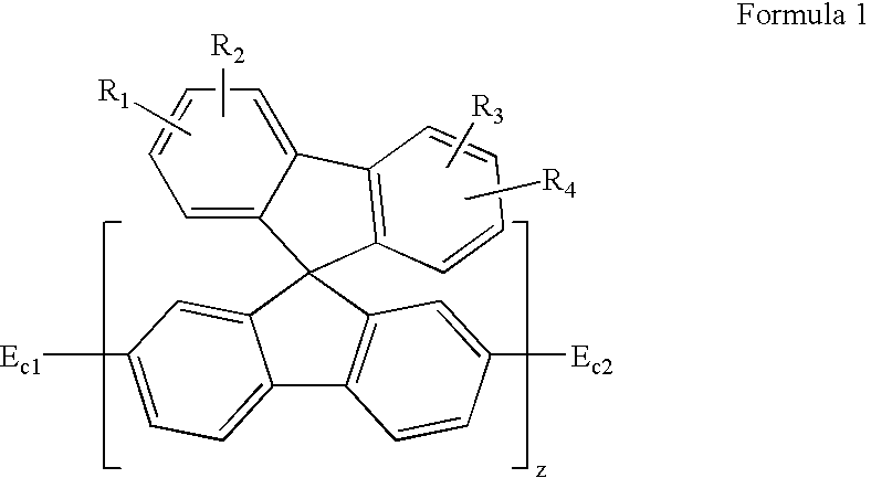
[0012] It is further an object of the present invention to provide a spirofluorene-based polymer which has a high charge transport capability and blue light-emitting property, and has thermal, optical and electrical stability due to introduced functional moieties substituted by fluorine having an electrical property into the ends of the polymer.
[0013] It is another object of the present invention to provide an organic electroluminescent device which has improved efficiency, driving voltage and color purity by using an organic layer using the above spirofluorene-based polymer.

Problems solved by technology

However, the device using polymer compounds has several problems, including low color purity, high driving voltage and low efficiency.
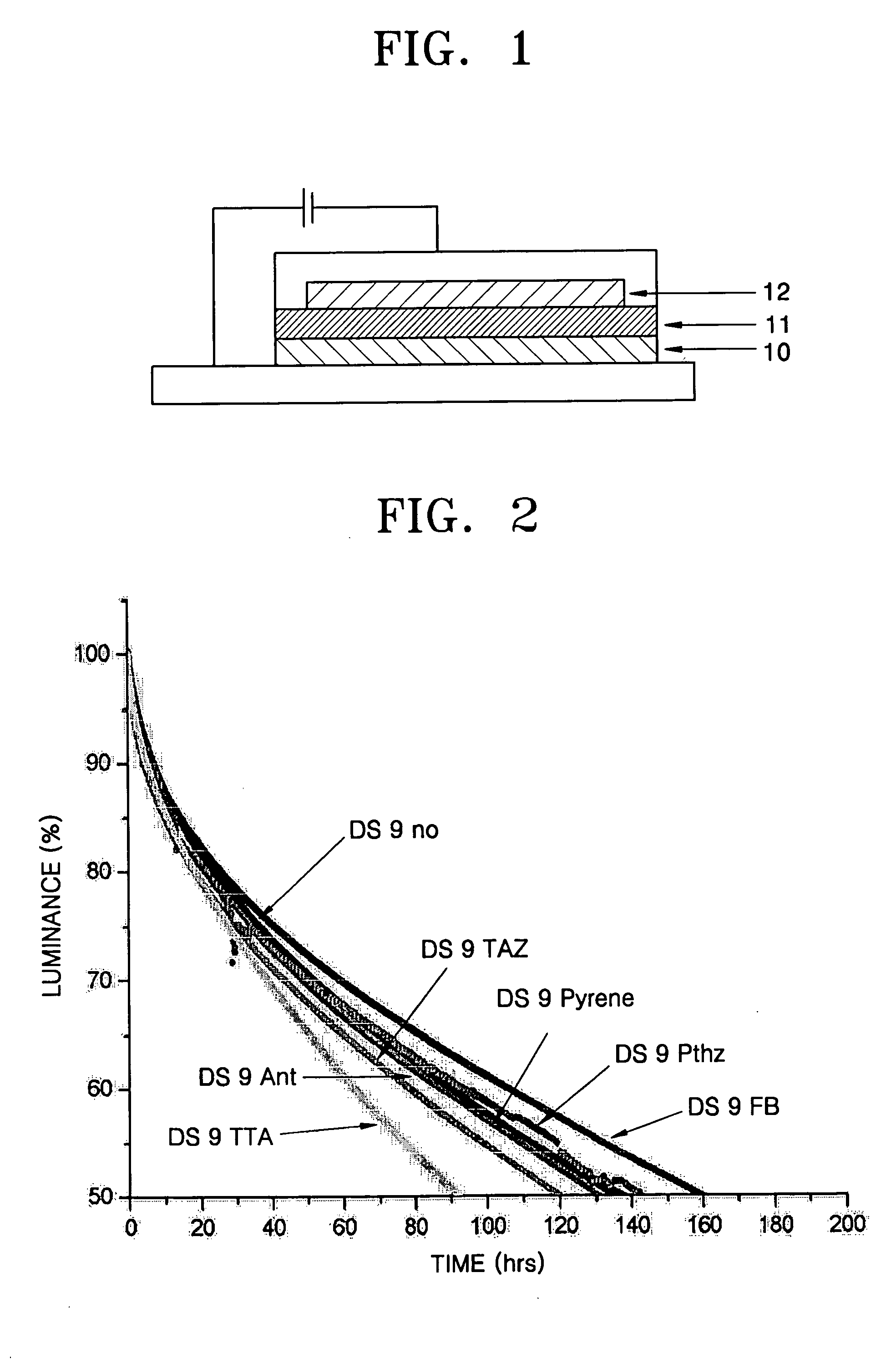
However, due to the electromers resulting from oxidation by light, a defect in the polymer backbone, and the interaction between molecules due to the remaining active ends of polymer compounds after polymerization, the lifetime of the materials is insufficient.
Thus, the short lifetime of blue light-emitting polymer has inhibited the development of electroluminescent display devices using the polymer.
However, the lifetime stability of the device is not sufficient.
(J. I. Lee, G. Klaerner and R. D. Miller, “Oxidative Stability and Its Effect on the Photoluminescence of Poly(Fluorene) Derivatives: End Group Effects,” Chem. Mater. 11, 1083 (1999)) However, this method could not overcome the problem that a position of C-9 was thermally unstable under the applied voltage, thus changing its color purity.
Introduction of end cappers has been in most cases limited to fluorene-containing polymers, and the known end cappers have insufficient effect on improving lifetime.

Method used


Image

  • Spirofluorene-based polymer and organic electroluminescent device using the same
  • Spirofluorene-based polymer and organic electroluminescent device using the same
  • Spirofluorene-based polymer and organic electroluminescent device using the same

Examples


example 1

Manufacture of Organic Electroluminescent Device

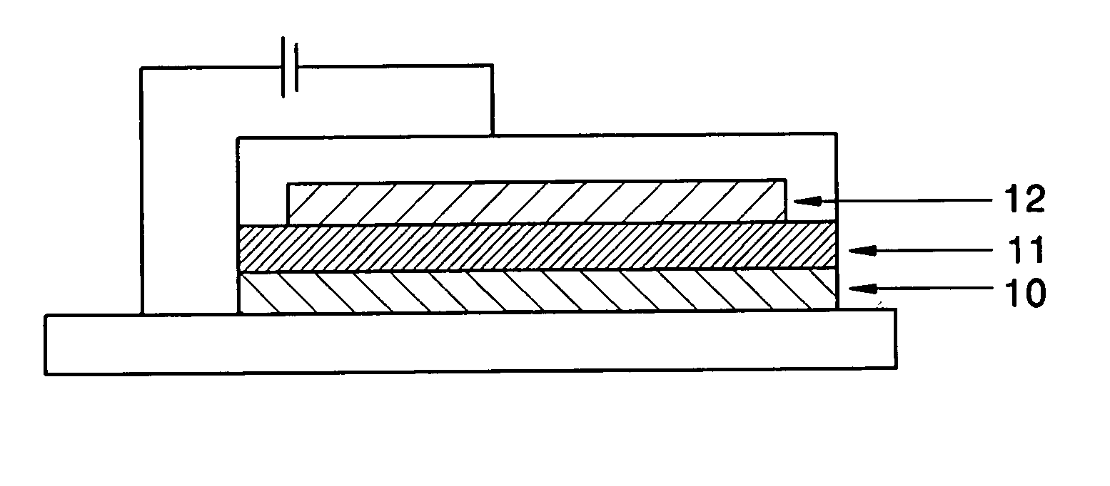
[0066] An electroluminescent (EL) device was manufactured using the polymer of formula 5 prepared according to Synthesis 1, as follows.

[0067] A transparent electrode substrate of glass coated with ITO (indium-tin oxide) was first cleaned. Then the ITO was patterned by using a photoresist resin and an etchant, and the resulting substrate was cleaned again. Batron P 4083 (available from Bayer) as a conductive buffer layer was coated onto the substrate to a thickness of about 800 Å, and then baked at 180° C. for about 1 hour. A solution for an electroluminescent layer was prepared by dissolving 0.1 parts by weight of the polymer of formula 5 in 99.9 parts by weight of toluene and then filtering through a 0.2 mm filter. The solution was spin coated onto the above buffer layer. After baking, the solvent was removed in a vacuum oven to form a thin film of the polymer. In the spin coating, the concentration of the polymer solution and the s...


PUM

PropertyMeasurementUnit
Timeaaaaaaaaaa
Capacitanceaaaaaaaaaa
Timeaaaaaaaaaa

Abstract

A spirofluorene-based polymer which contains a spirofluorene structure as a basic unit and which is end-capped with functional moieties substituted by fluorine, and an organic electroluminescent device using an organic layer using the spirofluorene-based polymer. The organic electroluminescent device has improved efficiency, reduced driving voltage, and excellent thermal, optical and electrical stability.

Description

CLAIM OF PRIORITY [0001] This application claims the benefit of Korean Patent Application No. 2004-4986, filed on Jan. 27, 2004, in the Korean Intellectual Property Office, the disclosure of which is incorporated herein in its entirety by reference. BACKGROUND OF THE INVENTION [0002] 1. Field of the Invention [0003] The present invention relates to a spirofluorene-based polymer and an organic electroluminescent device using the same, and more particularly to a spirofluorene-based polymer containing a spirofluorene structure as a basic unit, which has a high charge transport capability and blue light-emitting property, and has thermal, optical and electrical stability due to introduced functional moieties substituted by fluorine having an electrical property into the ends of the polymer, and an organic electroluminescent device using an organic layer containing the spirofluorene-based polymer. The device has improved efficiency and color purity and reduced driving voltage. [0004] 2. ...

Claims


Application Information

Patent Timeline
IPC IPC(8): B32B19/00H01L51/50C07C13/72C08G61/00C09K11/06H01L51/00H05B33/14
CPCC09K11/06C09K2211/1416C09K2211/1433H05B33/14H01L51/0043H01L51/5012H01L51/0039Y10S428/917H10K85/115H10K85/151H10K50/11A47F7/146A47F5/10A47F7/147
Inventor PARK, SANG-HOONNOH, TAE-YONGKIM, SANG-YEOLPU, LYONG-SUNLEE, SOO-HYOUNGKANG, IN-NAMSON, JHUN-MO
Owner SAMSUNG DISPLAY CO LTD
Learn More