High reflectivity atmospheric pressure furnace for preventing contamination of a work piece

a technology of high reflectivity and atmospheric pressure furnace, which is applied in the direction of furnaces, muffle furnaces, lighting and heating apparatus, etc., can solve the problems of cold process chamber and hot look, and achieve the effect of improving the performance of the substrate, reducing the amount of contamination, and increasing the purity

Inactive Publication Date: 2005-08-04
SOLAICX
View PDF8 Cites 47 Cited by
  • Summary
  • Abstract
  • Description
  • Claims
  • Application Information

AI Technical Summary

Benefits of technology

[0045] A further aspect enables surface coatings of higher purity to be deposited on a substrate due to the 1200° C. process temperature achieved by the invention. This can upgrade the performance of the substrate in terms of optical qualities, wear characteristics or electrical qualities. For example, an aspect of the invention enables a surface layer of silicon to be deposited under conditions that provide substantially higher purity with respect to a silicon substrate. The high temperature process makes the deposited silicon more crystalline, but the crystals orient themselves with respect to the structure of the underlying crystals in the substrate. This has particular application to the cost effective production of solar cells. Also, formerly cost sensitive PN junctions for photovoltaic devices now can be produced economically with high throughput.

Problems solved by technology

In other words, the process chamber is actually cold, but it looks hot.

Method used


Image

  • High reflectivity atmospheric pressure furnace for preventing contamination of a work piece
  • High reflectivity atmospheric pressure furnace for preventing contamination of a work piece
  • High reflectivity atmospheric pressure furnace for preventing contamination of a work piece

Examples


Embodiment Construction

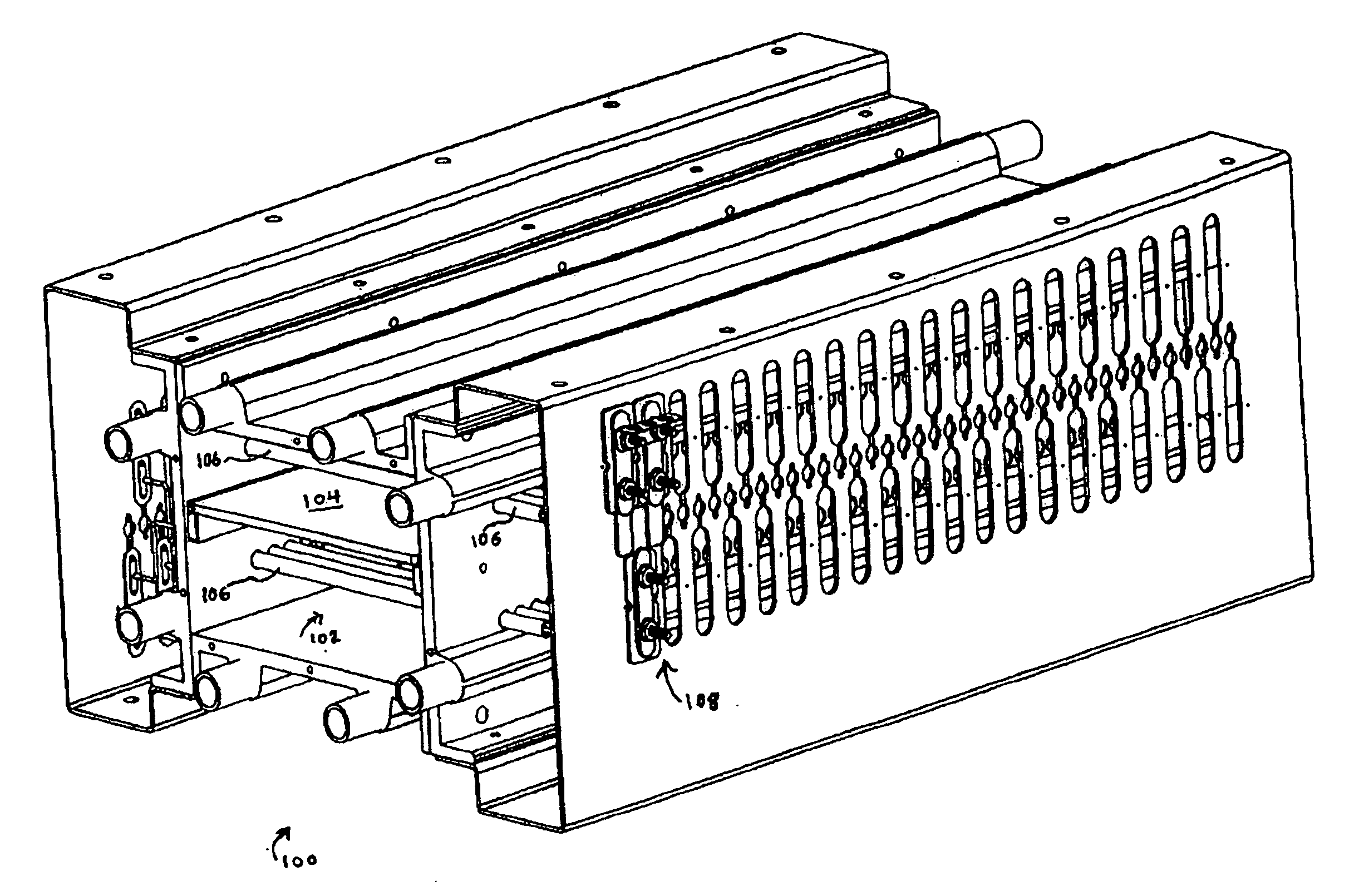
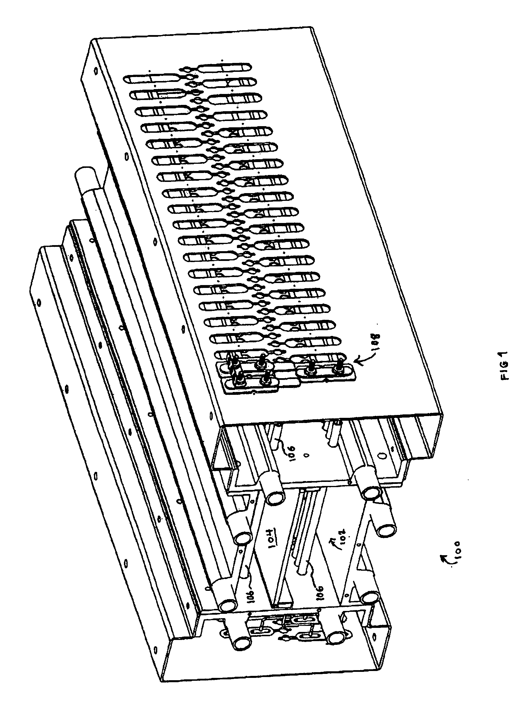
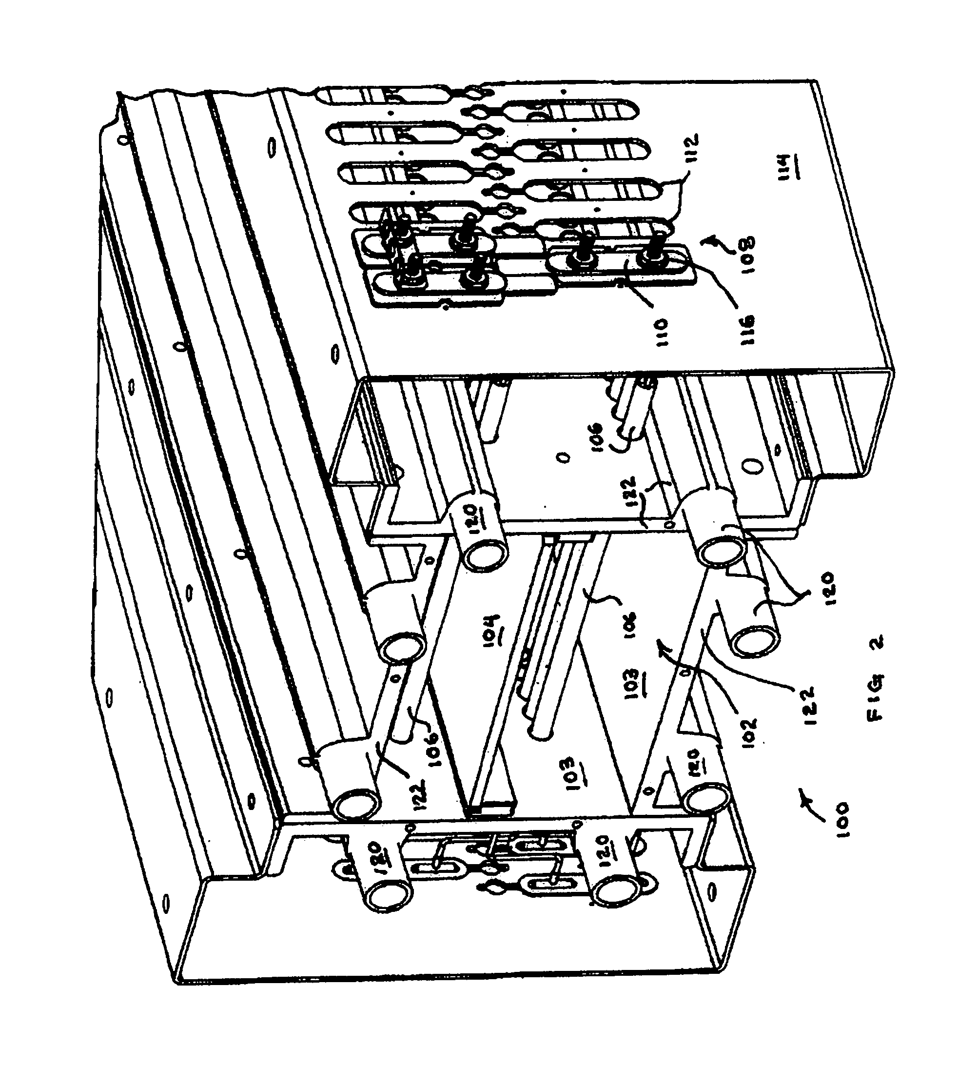
[0061] Reducing Source Temperature Required To Heat A Workpiece Referring to FIGS. 1, 2 and 3, a furnace 100 is provided that includes a process chamber 102 for accepting a workpiece 104, typically a semiconductor substrate, for processing. A plurality of heating elements 106 are disposed in first and second substantially parallel banks or arrays, above and beneath work piece for evenly heating the workpiece. The heating elements have a threaded terminal end 108 disposed in a ceramic spacer and insulator 110 that is conformably received in an aperture 112 in a side wall surface 114 for holding the distal ends of heating elements. The threaded end includes an attachment means, such as a locking nut 116 for attaching a lead to a source of electric power.

[0062] Referring to FIG. 1, an objective of the invention is to minimize the above described problems of conventional furnaces by identifying a thermal design that would reduce the heating element temperature. As mentioned, the heatin...


PUM

PropertyMeasurementUnit
temperatureaaaaaaaaaa
temperaturesaaaaaaaaaa
temperatureaaaaaaaaaa

Abstract

A furnace incorporating a novel thermal design is disclosed. Heating element temperature is reduced compared to conventional designs while providing a precisely controllable process temperature in the range 1000-1400 degrees centigrade. A plurality of Kanthal heating elements are arranged in a planar array as close to the work as possible, thus approximating an isothermal condition with respect to the work. The process chamber is made of aluminum and its internal surfaces are highly polished to reflect heat. The chamber walls have built in active cooling to carry away non-reflected heat and preserve high reflectivity. The heating elements are modular to facilitate removal and replacement without disassembly of the furnace. The configuration of the heating elements is linear rather than coiled and the temperature is monitored directly by measuring the electrical resistance of the Kanthal wires.

Description

CROSS-REFERENCE TO RELATED APPLICATION [0001] This patent application claims the benefit of U.S. provisional patent application Ser. No. 60 / 445,562, filed Feb. 7, 2003, which is incorporated herein by reference.BACKGROUND [0002] 1. Field of the Invention [0003] The field of the invention generally relates to a furnace for the formation of highly controlled, high purity films on a variety of substrates. In particular, the field of the invention relates to a high reflectivity furnace for chemical vapor deposition processes for the formation of source / drain junctions on a substrate at process temperatures reaching 1200° C. or more, at atmospheric pressure. The furnace achieves contamination-free heating of a work piece by using reflective heat containment rather than conventional thermal insulation and facilitates continuous processing with high throughput. [0004] 2. Background of Related Art [0005] The manufacture of semiconductor devices requires the deposition of thin dielectric fil...

Claims


Application Information

Patent Timeline
Patent Type & Authority Applications(United States)
IPC IPC(8): C23C16/00C23C16/46F27B5/04F27B5/14F27B5/18F27B9/04F27B9/06F27B9/20F27B9/36F27B17/00F27D11/02F27D99/00H01L21/00
CPCC23C16/4411C23C16/46F27B5/04F27B5/14F27B5/18F27B9/045H01L21/67109F27B9/20F27B9/36F27B17/0025F27D11/02F27D99/0006F27B9/062
Inventor GRALENSKI, NICHOLAS
Owner SOLAICX
Why Eureka
Try Eureka