
Method and apparatus for making a stamper for patterning CDs and DVDs

a patterning cd and dvd technology, applied in the field of stampers, can solve the problems of high cost, complicated and expensive, and high cost of plating process and glass substrate starting material, and achieve the effect of reducing or no sacrifice in data storage density and reducing the minimum feature pitch siz

Inactive Publication Date: 2005-08-04
WD MEDIA
View PDF22 Cites 76 Cited by
  • Summary
  • Abstract
  • Description
  • Claims
  • Application Information

AI Technical Summary

Benefits of technology

[0021] Optionally, the resist can be “prebaked” (baked before being exposed) and / or baked after being exposed. This enhances the mechanical stability of the resist.
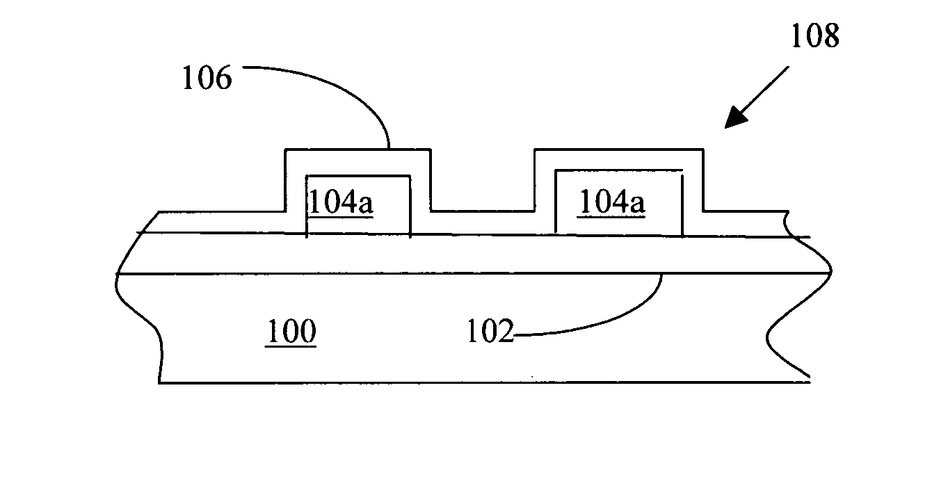
[0023] Advantageously, the stamper is provided without having to form most of the thickness of the stamper by a deposition process. Instead, a rolling process is used to form a large part of the stamper thickness. However, because a surface of the stamper is formed by deposition, this surface is very smooth, so that it is unnecessary to perform a great amount of polishing.
[0030] If one merely substituted a photoresist-covered metallic substrate for a photoresist-covered glass substrate, the minimum feature pitch size that could be achieved would be larger than the corresponding minimum feature pitch size that could be achieved with photoresist on glass. Therefore, the data storage density that could be achieved using a metallic substrate would be degraded. Moreover, the cross section of the resultant pit or protrusion will not meet the requirements for the desired data density or polycarbonate molding process. This is because a laser interacts with a metallic substrate differently than with a glass substrate. By providing the above-mentioned light-insensitive layer between the metallic substrate and the photoresist, a smaller minimum feature pitch size and the desired pit or protrusion cross section can be achieved. Therefore, one can replace a glass substrate with a much less expensive metal substrate coated with the light-insensitive layer with reduced or no sacrifice in data storage density.
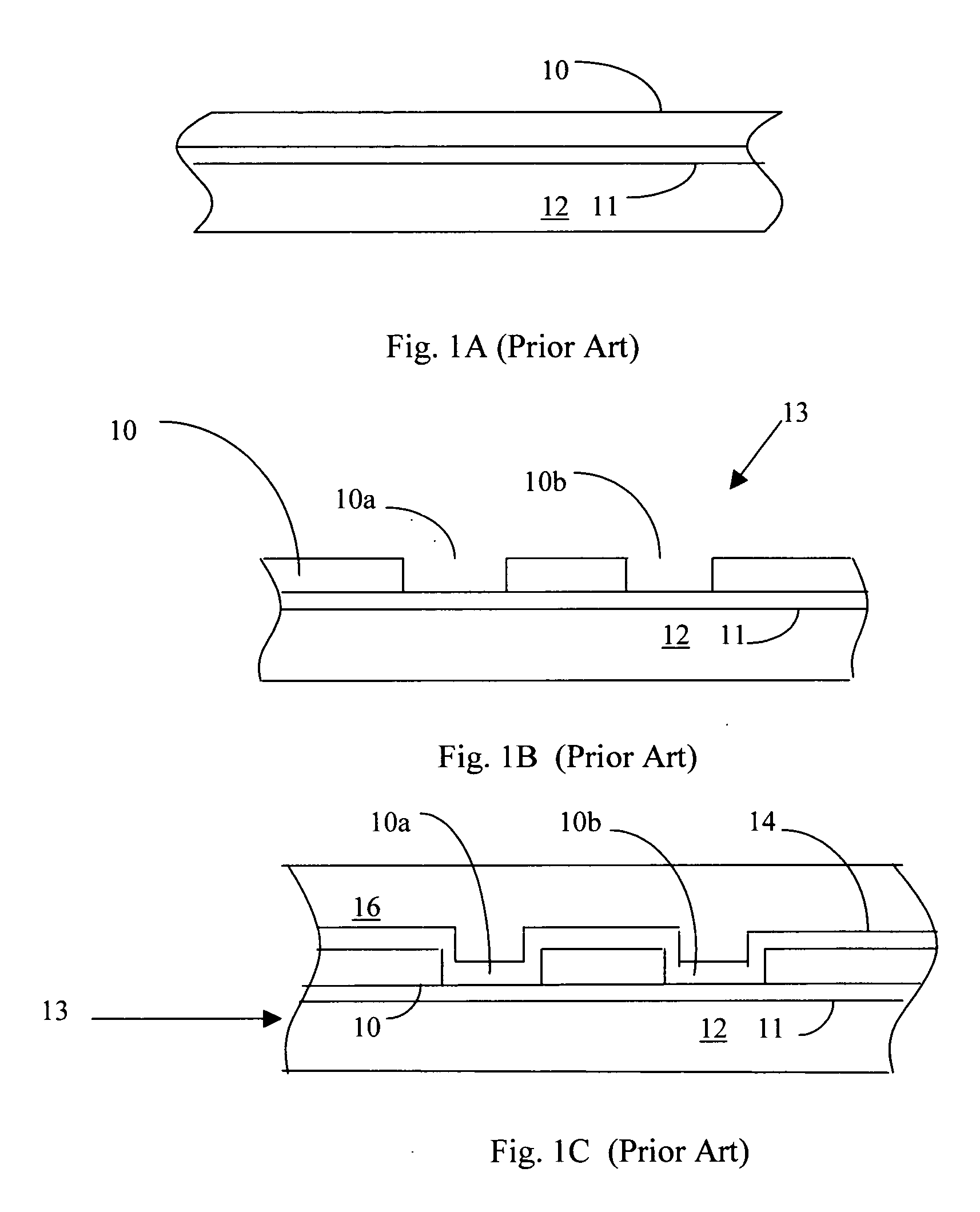
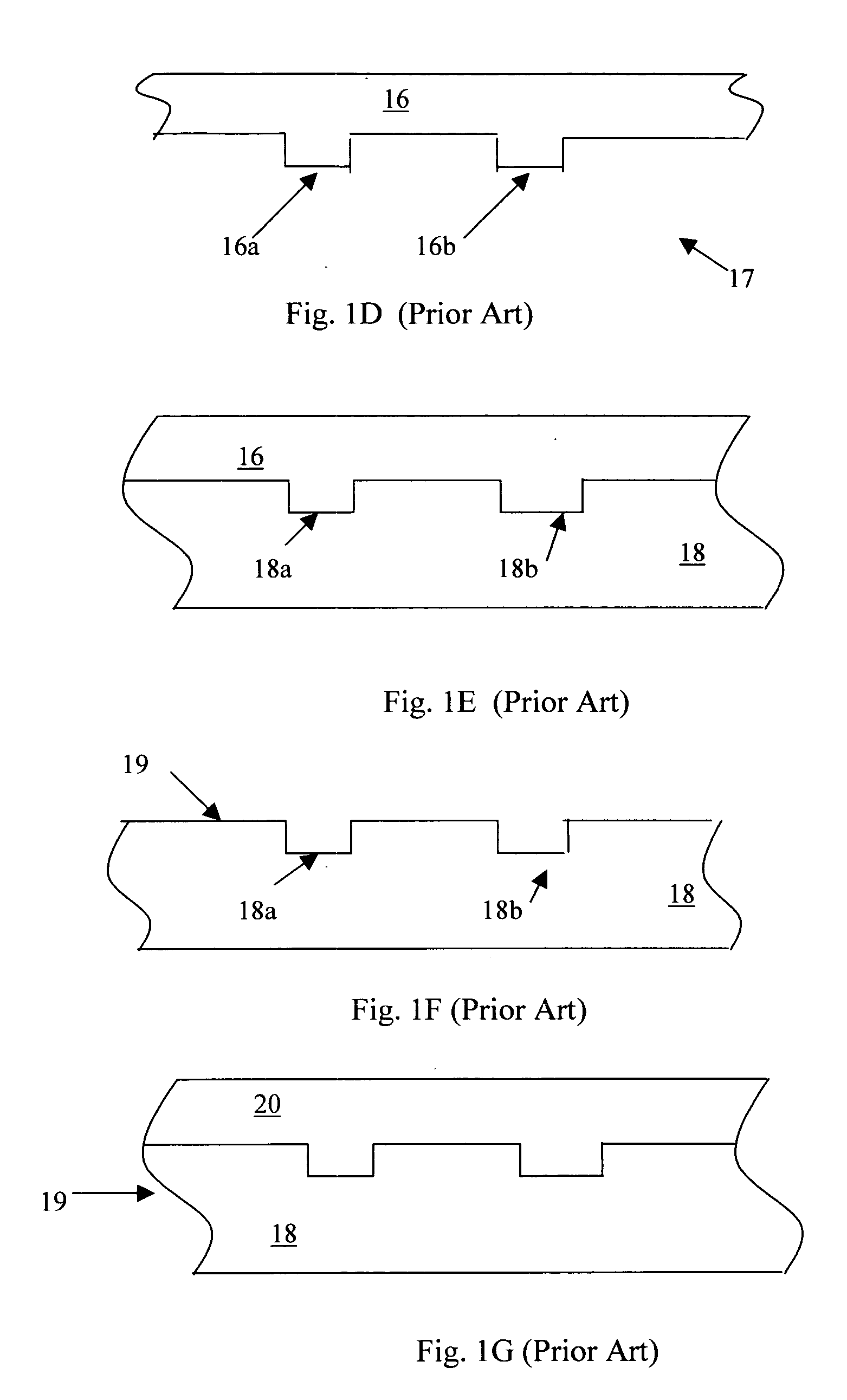
[0031] One can essentially use the polymer-coated metallic substrate in the process of FIGS. 1A to 1H in lieu of the more expensive glass substrate 12 without having to make substantial modifications to the patterning process. Since 95% of stamper manufacturing uses the method of FIGS. 1A to 1H, this represents a significant saving for the CD and DVD industry.
[0032] In a third embodiment of the invention, instead of using a metallic substrate covered with a light insensitive layer, the surface of the metallic substrate is made substantially non-reflective of the laser light used to expose the photoresist. For reasons described below, this is an alternative method for reducing the minimum feature pitch size that can be achieved in the photoresist compared to what would be achieved if the photoresist was directly applied to a reflective metallic substrate.

Problems solved by technology

While this procedure is adequate for producing optical media, it is complicated and expensive.
In particular, the plating processes and the glass substrate starting material are expensive.
While the above-described process provides adequate results, it is also expensive.
For example, forming nickel layer 34 by plating is expensive.
Unfortunately, substrates formed by rolling have many surface defects that would have to be removed by polishing.
Such polishing would be excessively expensive.
However, because a surface of the stamper is formed by deposition, this surface is very smooth, so that it is unnecessary to perform a great amount of polishing.
If glass substrate 12 fractures while it is within laser patterning equipment, removing broken pieces of glass from the equipment can be a time-consuming task.
Moreover, the cross section of the resultant pit or protrusion will not meet the requirements for the desired data density or polycarbonate molding process.

Method used


Image

  • Method and apparatus for making a stamper for patterning CDs and DVDs
  • Method and apparatus for making a stamper for patterning CDs and DVDs
  • Method and apparatus for making a stamper for patterning CDs and DVDs

Examples


Embodiment Construction

[0039] Referring to FIG. 4A, a method in accordance with one embodiment of our invention includes providing a sheet 100. Sheet 100 is typically metallic, and is formed by rolling. During rolling, an ingot of material is fed through rollers 101 to form sheet 100. (Although only two pairs of rollers are shown in FIG. 4A, typically more than two pairs of rollers are used during this process.) As the material passes through the rollers, it becomes progressively thinner until it is in the form of sheet 100. Sheet 100 can be a metal such as a spinodal copper alloy. (Spinodal structures are discussed by D. E. Laughlin and W. A. Soffa in “Spinodal Structures”, Metals Handbook, Ninth Edition: Volume 9, Metallography and Microstructures, American Society for Metals, pages 652-654 (1985), incorporated herein by reference.) Spinodal structures have the advantage of being bendable without distortion. However, sheet 100 can be other materials as well, e.g. nickel, stainless steel or brass. In one...


PUM

PropertyMeasurementUnit
thickaaaaaaaaaa
wavelengthaaaaaaaaaa

Abstract

A method for forming a stamper used in the manufacture of CDs, DVDs, and other types of optical disks comprises forming a substrate by rolling. A layer of material is deposited (e.g. by plating) onto the substrate. Thereafter, a resist layer is formed on the layer of material and patterned. Because the substrate is formed by rolling, it is relatively inexpensive to form the substrate to a desired thickness. Because the layer of material is formed by deposition (e.g. plating), it is relatively inexpensive to ensure that the layer has a very smooth surface (i.e. without necessitating a great deal of polishing).

Description

CROSS-REFERENCE TO RELATED APPLICATIONS [0001] This application is a continuation-in-part of our copending U.S. patent application Ser. No. 10 / 837,859 (filed May 3, 2004), which in turn claims priority based on U.S. Provisional Patent Application Ser. No. 60 / 535,380 (filed Jan. 8, 2004).BACKGROUND OF THE INVENTION [0002] This invention pertains to stampers used to manufacture optical data storage media such as CDs and DVDs and methods for making such stampers. (As used herein, optical media includes magneto-optic, phase change and dye based media as well as other types of optical media.) [0003] It is known in the art to use “stampers” to make optical data storage devices. Stampers are discussed, for example, by Boomaars, “The Key to Mastering the In-House Solution”, published in April, 2003, One to One, pages 63-64, incorporated by reference. See also EP 0 995 193 B1, EP 0 986 813 B1 and U.S. Pat. No. 6,238,846. [0004]FIGS. 1A to 1H schematically illustrate in cross section a first ...

Claims


Application Information

Patent Timeline
Patent Type & Authority Applications(United States)
IPC IPC(8): G11B7/26
CPCG11B7/263
Inventor BAJOREK, CHRISTOPHER H.CALCATERRA, ANTHONY D.
Owner WD MEDIA
Learn More