Dimmer circuit with improved inductive load imbalance protection

a technology of inductive load and inductive load, applied in the direction of electrical variable regulation, sustainable buildings, instruments, etc., can solve the problems of reducing the sensitivity of the triacs axe, reducing the sensitivity of the load type, and reducing the robustness of the sensitive triacs axe, so as to reduce the likelihood of load imbalance using expensive components

Inactive Publication Date: 2005-08-04
CLIPSAL INTEGRATED SYST
View PDF10 Cites 37 Cited by
  • Summary
  • Abstract
  • Description
  • Claims
  • Application Information

AI Technical Summary

Benefits of technology

[0015] Optionally, the circuit control means causes the dimmer circuit to reduce a conduction angle of the dimmer circuit to a point where the DC component reduces to below a preset threshold.
[0016] The invention therefore eliminates the need for traditional methods of attempting to reduce the likelihood of load imbalance using expensive components.

Problems solved by technology

Such a device offers advantages of relatively low conduction losses and high robustness, but has the disadvantage of operating sensitivity to load type.
This can rapidly lead to overheating of primary windings of the transformer.
Sensitive triacs axe comparatively less robust and therefore not as suitable for universal dining applications.

Method used


Image

  • Dimmer circuit with improved inductive load imbalance protection
  • Dimmer circuit with improved inductive load imbalance protection
  • Dimmer circuit with improved inductive load imbalance protection

Examples


Embodiment Construction

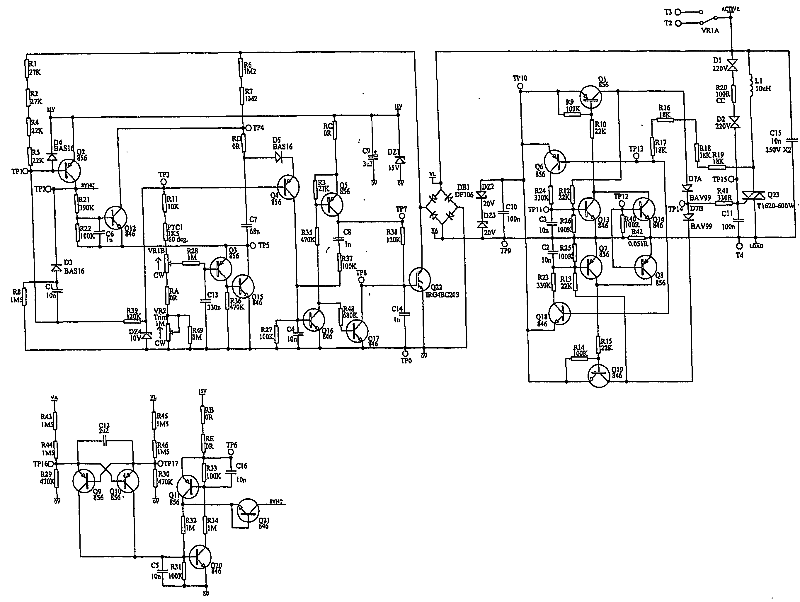
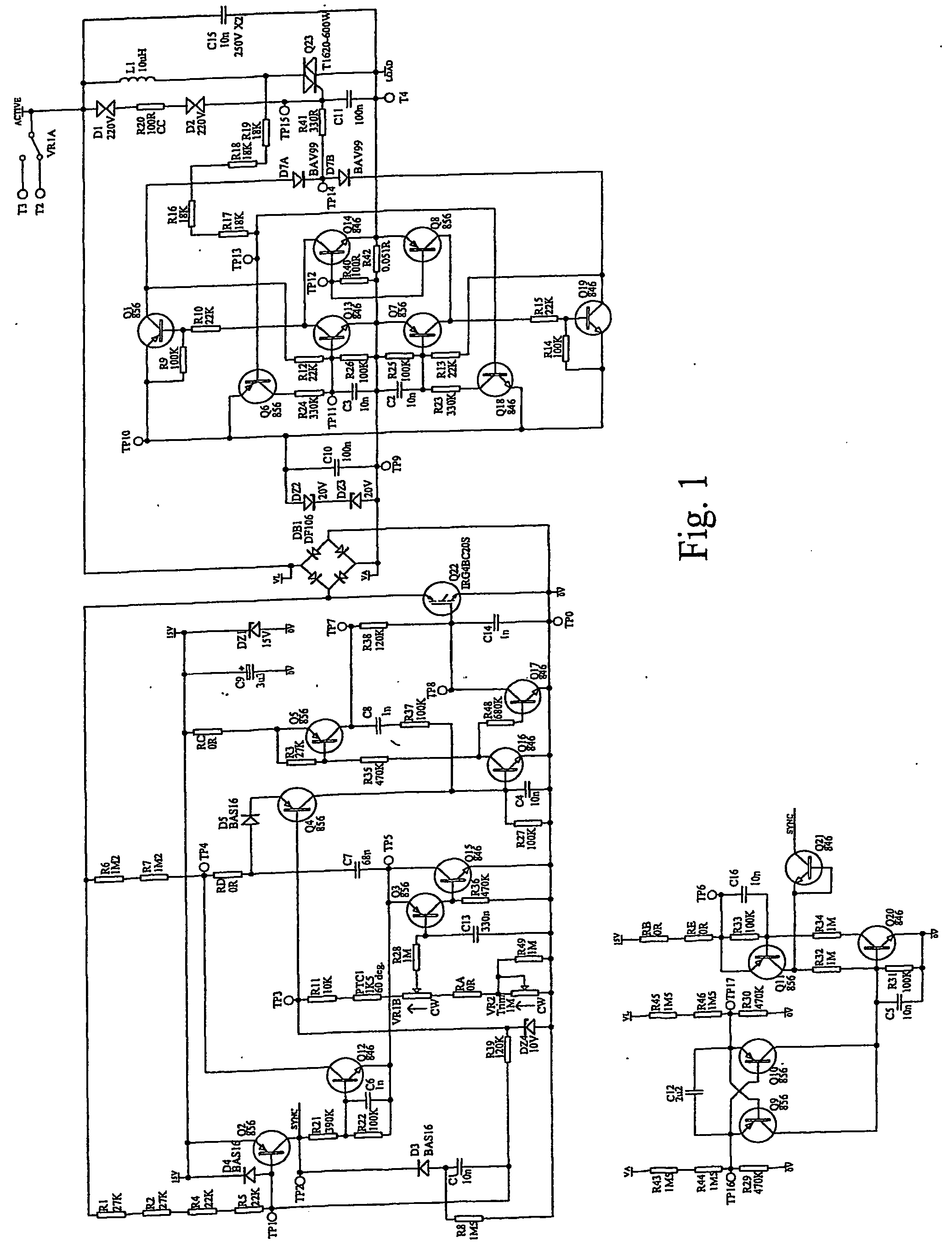
[0022] A preferred circuit design of a 2-wire, leading edge phase control light dimmer / fan speed controller is shown in FIG. 1. The design shown in FIG. 1 is particularly effective in that it is electromagnetic compatible (EMI compliant). This refers to the amount of electromagnetic interference EMI) that is generated by the circuit. The amount of radiation generated by dimming circuits due to the high frequency switching of the circuit is heavily regulated and such circuits must not exceed the regulated level of EMI.

[0023] The circuit design of FIG. 1 controls the level of EMI generated by the circuit via active control of the rate of rise of load voltage at each main half cycle. A power semiconductor in the form of an IGBT is used for this function. The IGBT and associated drive control circuitry is connected to the DC side of a diode bridge to allow control of polarities of mains voltage.

[0024] A power triac is used to handle the load current once the IGBT has performed the req...


PUM


Abstract

A protection circuit for protecting a dimmer circuit controlling an inductive load including an imbalance detector for detecting an asymetrical operation in the load and circuit control means for causing the dimmer circuit to reduce a DC component in the load upon detection of the asymetrical operation. A load imbalance detector is also disclosed having a load DC component detector, a comparator and a signal generating means for generating means for generating a circuit shut down signal if the DC component exceeds a pre-set DC threshold.

Description

TECHNICAL FIELD [0001] This invention relates to circuit arrangements for controlling the power provided to a load and in particular, to dimmer circuits for controlling, for example, the luminosity of a light or the speed of a fan. BACKGROUND TO THE INVENTION [0002] Dimmer circuits are used to control the power provided to a load such as a light or electric motor from a power source such as mains. Such circuits often use a technique referred to as phase controlled dimming. This allows power provided to the load to be controlled by varying the amount of time that a switch connecting the load to the power source is conducting during a given cycle. [0003] For example, if voltage provided by the power source can be represented by a sine wave, then maximum power is provided to the load if the switch connecting the load to the power source is on at all times. In this way the, the total energy, of the power source is transferred to the load. If the switch is turned off for a portion of eac...

Claims


Application Information

Patent Timeline
Patent Type & Authority Applications(United States)
IPC IPC(8): G05F5/02H02M7/12H02M1/08H02M1/15H03K17/13H03K17/16H05B1/00H05B39/04H05B39/08H05B41/24H05B41/38H05B47/10
CPCH02M1/081H02M1/15H02M1/40H02M5/2573H02H3/253H05B39/08Y02B20/148Y10S315/04H05B39/048Y02B20/00G05F5/00
Inventor VANDERZON, JAMES ROBERT
Owner CLIPSAL INTEGRATED SYST
Why Eureka
Try Eureka