Boost pressure estimation apparatus for internal combustion engine with supercharger

a technology of internal combustion engine and supercharger, which is applied in the direction of combustion engine, electric control, machines/engines, etc., can solve the problems of reducing the accuracy of detection, affecting the accuracy of boost pressure estimation, etc., to achieve accurate estimation, accurate calculation, accurate estimation

Active Publication Date: 2005-08-11
DENSO CORP
View PDF11 Cites 37 Cited by
  • Summary
  • Abstract
  • Description
  • Claims
  • Application Information

AI Technical Summary

Benefits of technology

[0011] In this case, the amount of gas passing through the waste gate valve varies with the opening of the waste gate valve. Accordingly, the turbine-supplied gas amount can be accurately calculated by using the intake air amount and the opening of the waste gate valve. Depending on the turbine-supplied gas amount, the exhaust turbine's rotational speed (compressor's rotational speed) changes to change the boost pressure. The boost pressure estimation method according to the present invention can accurately estimate the boost pr

Problems solved by technology

Depending on cases, the boost pressure sensor may fail or degrade the detection accuracy.
It becomes impossible to provide control or pro

Method used


Image

  • Boost pressure estimation apparatus for internal combustion engine with supercharger
  • Boost pressure estimation apparatus for internal combustion engine with supercharger
  • Boost pressure estimation apparatus for internal combustion engine with supercharger

Examples


embodiment 1

[0034] Embodiment 1 of the present invention is described with reference to FIGS. 1 through 7.

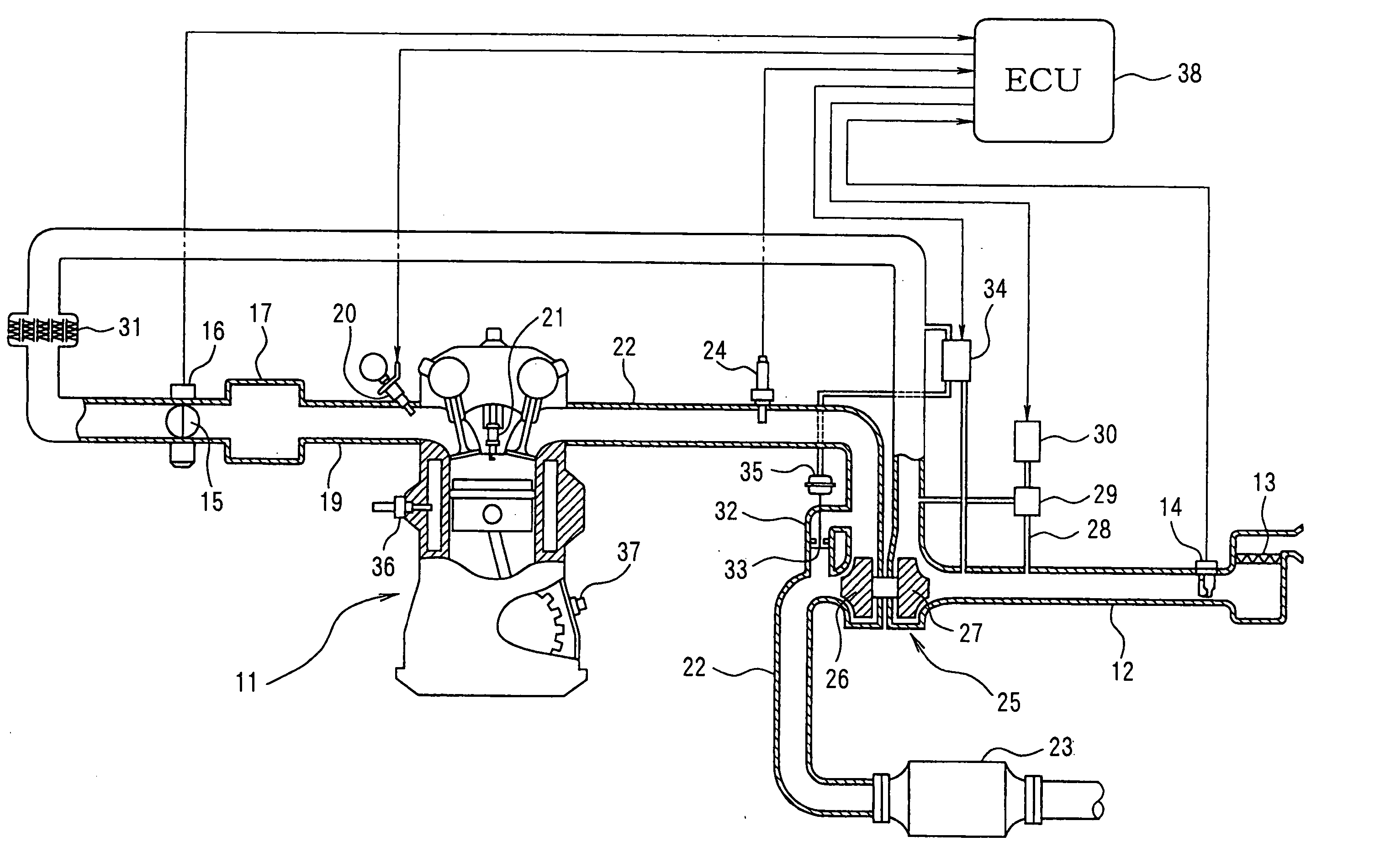
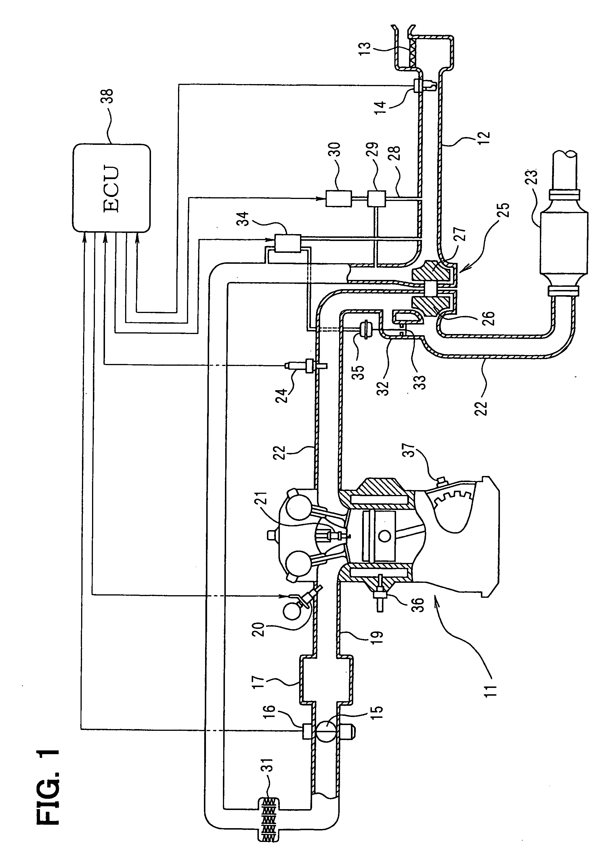
[0035] An overall construction of the engine control system is described with reference to FIG. 1. An air cleaner 13 is provided at the highest upstream of an intake pipe 12 (intake pipe) of an engine 11 as an internal combustion engine. The downstream of the air cleaner is provided an air flow meter 14 (means for detecting intake air amount) that detects the amount of intake air. The downstream of the air flow meter 14 is provided with a throttle valve 15 and a throttle opening sensor 16. A DC motor or the like is used to adjust the opening of the throttle valve 15. The throttle opening sensor 16 detects the throttle opening.

[0036] Further, a surge tank 17 is provided at the downstream of the throttle valve 15. The surge tank 17 is provided with an intake manifold 19 that introduces air into each cylinder of the engine 11. A fuel injection valve 20 to inject fuel is attached near an inta...

embodiment 2

[0061] Embodiment 2 of the present invention will be described with reference to FIGS. 8 through 17.

[0062] As shown in FIGS. 16A and 16B, the intake air amount Ai (exhaust gas amount) of the engine 11 suddenly changes during transient states such as acceleration and deceleration. Compared to a change in the turbine-supplied gas amount Gt, a change in the exhaust turbine's rotational speed is subject to a delay due to inertia of the exhaust turbine 26. Accordingly, a delay occurs in a change in the boost pressure compared to a change in the turbine-supplied gas amount Gt.

[0063] As shown in FIG. 17A, the boost pressure rises during deceleration from the supercharging state. To prevent this, the ABV 29 is opened to decrease the boost pressure during the deceleration.

[0064] Further, as shown in FIG. 17B, there may be a difference between the exhaust turbine's rotational speed and the boost pressure when the ABV 29 is opened and closed.

[0065] In addition, an IC pressure loss (an inta...

embodiment 3

[0092] The following describes embodiment 3 of the present invention with reference to FIGS. 18 and 19.

[0093] As shown in FIG. 18, embodiment 3 provides two exhaust pipes 39 (exhaust pipes) corresponding to two cylinder groups. An air-fuel ratio sensor 24 is provided for the exhaust pipe 39 in each cylinder group. Corresponding to the two exhaust pipes 39, two exhaust turbine superchargers 25 are mounted on the engine 11. Each supercharger 25 is provided with the exhaust turbine 26 in each of the two exhaust pipes 39. A branch intake pipe 40 (intake pipe) branches into two portions between the air flow meter 14 and the throttle valve 15 in the intake pipe 12. Each branch intake pipe 40 is provided with the compressor 27. The exhaust bypass pipe 32 is provided for each of the two exhaust pipes 39. Each exhaust bypass pipe 32 is provided with the WGV 33 and an actuator 35. The common VSV 34 for WGV controls the WGVs 33 and the actuators 35. The remainder of the system construction is...


PUM


Abstract

An opening is provided for an exhaust bypass pipe that bypasses an exhaust turbine of an exhaust turbine supercharger. According to the opening, an exhaust gas amount bypassing the exhaust turbine is calculated. An exhaust gas amount supplied to the exhaust turbine is found by subtracting the waste-gate-valve-passing gas amount from an intake air amount (exhaust gas amount) detected by the air flow meter. A rotational speed of the exhaust turbine is calculated from this turbine-supplied gas amount. An estimated boost pressure is calculated from this rotational speed of the exhaust turbine. Consequently, a boost pressure can be accurately estimated without using a boost pressure sensor even under such conditions as to disable detection of boost pressures or degrade the detection accuracy in a system using a conventional boost pressure sensor.

Description

CROSS-REFERENCE TO RELATED APPLICATION [0001] This application is based on Japanese Patent Application No. 2004-32692 filed on Feb. 9, 2004, the disclosure of which is incorporated herein by reference. FIELD OF THE INVENTION [0002] The present invention relates to a boost pressure estimation apparatus for an internal combustion engine with a supercharger, which estimates a boost pressure of the supercharger. BACKGROUND OF THE INVENTION [0003] Conventionally, some internal combustion engines for vehicles are equipped with an exhaust turbine supercharger (so-called turbo charger) to obtain high power. Generally, an exhaust turbine supercharger has the following construction. An exhaust turbine is provided within an exhaust pipe of the internal combustion engine and is connected to a compressor provided on an intake pipe. Kinetic energy of exhaust gas is used to rotatively drive the exhaust turbine. In this manner, the compressor is rotatively driven to supply intake air. [0004] The te...

Claims


Application Information

Patent Timeline
IPC IPC(8): F02B37/18F02B37/007F02B37/16F02D23/00F02D41/00F02D45/00
CPCF02B37/007F02B37/16F02B37/18Y02T10/144F02D41/187F02D2200/0408F02D41/0007Y02T10/12
Inventor FUKASAWA, OSAMUOBAYASHI, HIDEKI
Owner DENSO CORP
Why Eureka
Try Eureka