Heat exchanger for wasted heat with its cleaning apparatus

a technology of heat exchanger and cleaning apparatus, which is applied in the direction of lighting and heating apparatus, milk preservation, and cleaning using liquids, etc., can solve the problems of difficult cleaning of conduits and heat exchange pipes, and difficult heat transfer smoothly, so as to increase the heat recovery efficiency of waste heat, facilitate maintenance, and clean heat exchange pipes.

Active Publication Date: 2005-08-11
JUNG YANG JUN
View PDF8 Cites 21 Cited by
  • Summary
  • Abstract
  • Description
  • Claims
  • Application Information

AI Technical Summary

Benefits of technology

[0003] Accordingly, it is an object of the present invention to provide a waste heat recovery system with a cleaning apparatus, which can easily clean a heat exchange pipe and provide a convenient maintenance. Another object of the present invention is to provide a waste heat recovery system with a cleaning apparatus, which can increase a heat recovery efficiency of waste heat.

Problems solved by technology

However, in the conventional waste heat recovery system, the waste water is strained through a filter before being induced into the water tank to prevent stopping of the water tank or a flow channel due to foreign matters because foreign matters or wastes contained in the waste water are induced into the water tank.
However, the conventional waste heat recovery system has a problem in that it is difficult to transfer heat smoothly as the foreign matters are stained on the external surface of the heat exchange pipe or sludge is formed on the external surface of the heat exchange pipe in spite of installation of the filtering device while the waste heat recovery system is used for a long time.
However, it is difficult to clean a conduit and the heat exchange pipe since the conduit and the heat exchange pipe are in a spiral form or have a complicated shape to increase the surface area for heat transfer.

Method used


Image

  • Heat exchanger for wasted heat with its cleaning apparatus
  • Heat exchanger for wasted heat with its cleaning apparatus
  • Heat exchanger for wasted heat with its cleaning apparatus

Examples


Embodiment Construction

[0015] The present invention will now be described in detail in connection with preferred embodiments with reference to the accompanying drawings.

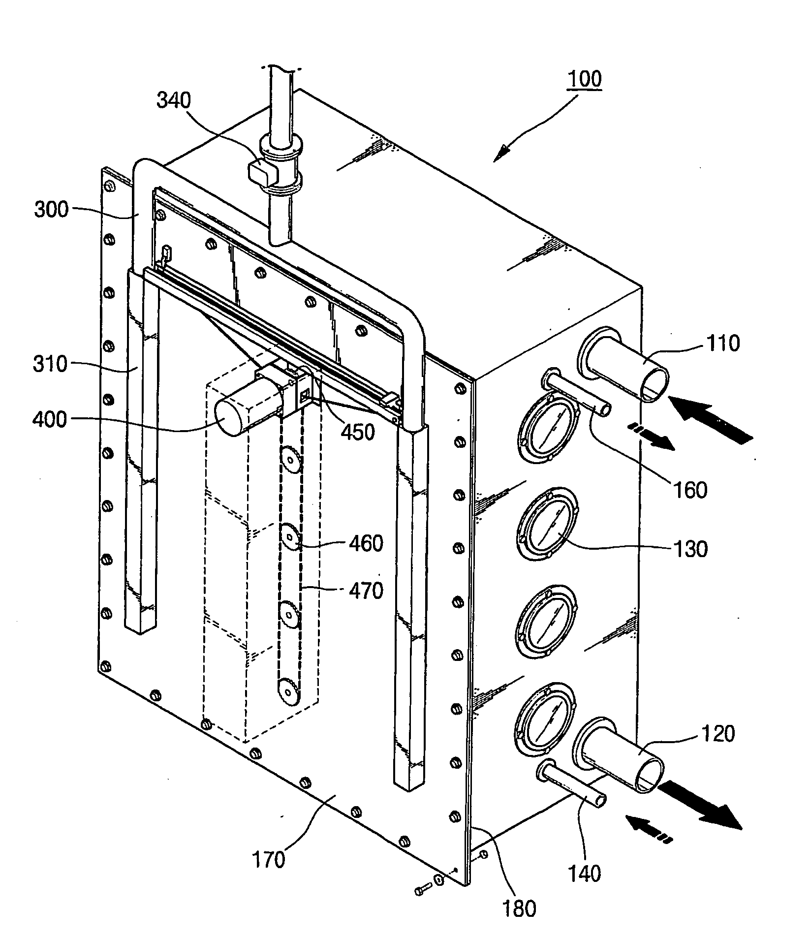
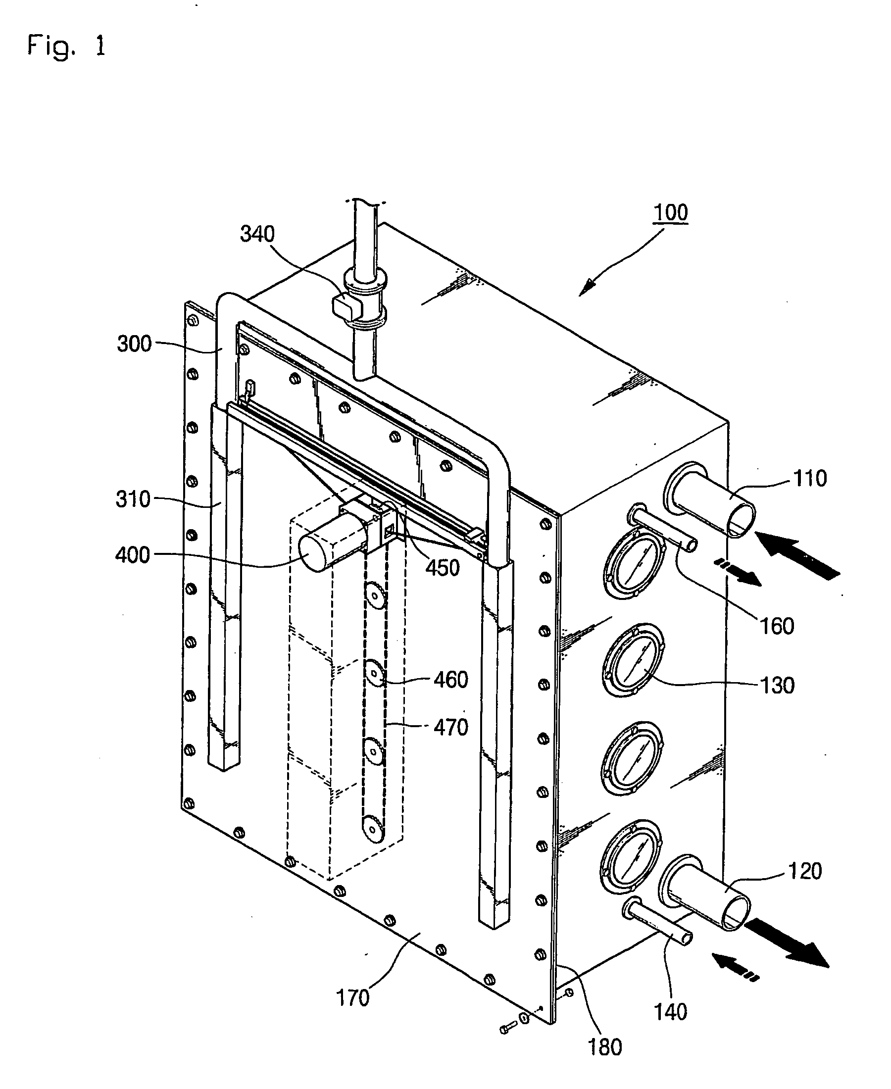
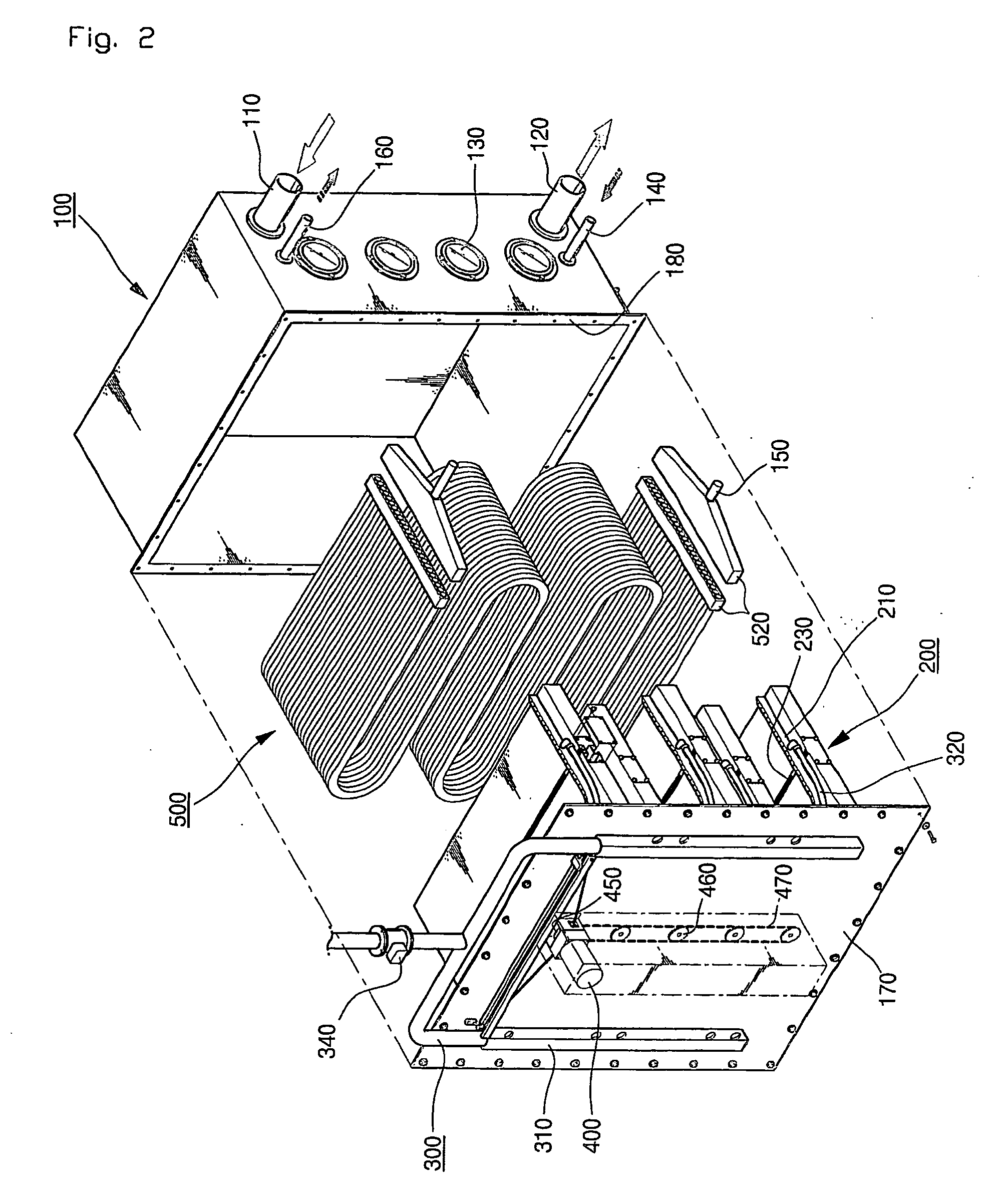
[0016] As shown in FIGS. 1 and 2, a waste heat recovery system includes: a tank 100; a number of heat exchange pipes 500 connected with one another in the form of a ‘S’ shape in multiple steps inside the tank 100 and having a number of city water flow pipes bound up into a bundle; circulation leading plates 200 mounted between the heat exchange pipes 500 to form waste water paths; a movable nozzle part mounted on the outer surface of the circulation leading plate 200 and connected with a high pressure water induction pipe 300; a nozzle driving part mounted inside the circulation leading plate for driving the movable nozzle part along a guide rail 230 formed on the circulation leading plate 200; a driving part mounted on the outer surface of an assembly plate 170 of the tank 100 for driving the nozzle driving part; and a position sensing p...


PUM


Abstract

Disclosed is a waste heat recovery system with a cleaning apparatus, which can effectively recover waste heat and easily clean the system, thereby increasing heat exchange efficiency and making its maintenance easy. The waste heat recovery system includes: a tank; heat exchange pipes connected with one another in the form of a ‘S’ shape in multiple steps inside the tank and having city water flow pipes bound up into a bundle; circulation leading plates mounted between the heat exchange pipes for inducing a flow of waste water; movable nozzles mounted on the circulation leading plates and connected with a high pressure water pipe for spraying high pressure water onto the surface of the heat exchange pipe or having a brush for cleaning the surface of the heat exchange pipe; a nozzle driving part for driving the movable nozzle by means of a driving motor; and waste water inlet and outlet for flowing hot waste water from the upper portion to the lower portion of the tank and city water inlet and outlet for flowing city water from the lower portion to the upper portion of the tank.

Description

TECHNICAL FIELD [0001] The present invention relates to a waste heat recovery system with a cleaning apparatus for recovering heat of water wasted from a public bath, a factory or a swimming pool, and more particularly, to a waste heat recovery system with a cleaning apparatus, which can allow an effective recovery of waste heat and an easy cleaning of the waste heat recovery system, thereby increasing heat exchange efficiency and providing an easy maintenance. BACKGROUND ART [0002] In general, a waste heat recovery system for reusing heat of water wasted from a place where a great deal of hot water is used, such as a public bath, a swimming pool, a fish-farm, or other place, heats cold water inside a heat exchange pipe in such a manner that the heat exchange pipe for carrying cold water is installed inside a water tank and waste water of high temperature discharged from the public bath is induced into the water tank so as to transfer heat between the heat exchange pipe and the wast...

Claims


Application Information

Patent Timeline
Patent Type & Authority Applications(United States)
IPC IPC(8): F28D7/08F28G1/02F28G1/16
CPCF28D7/08F28D7/087Y02B30/566F28G1/02F28G1/166F28D21/0012Y02B30/56F28G1/16
Inventor JUNG, A-RA
Owner JUNG YANG JUN
Why Eureka
Try Eureka