Inorganic scintillator

a scintillator and inorganic technology, applied in the field of inorganic scintillators, can solve the problems of luminous efficiency decline and luminous efficiency decline, and achieve the effects of shortening the fluorescence decay time easily and reliably, sufficient luminous efficiency, and sufficient luminous efficiency

Inactive Publication Date: 2005-08-11
HITACHI CHEM CO LTD
View PDF3 Cites 7 Cited by
  • Summary
  • Abstract
  • Description
  • Claims
  • Application Information

AI Technical Summary

Benefits of technology

[0018] Since cerium has a tetravalent ionization energy I of 3547 kJ·mol−1, the dopant having the tetravalent ionization energy satisfying the condition represented by expression (1) seems to be more likely to attain the tetravalent state than is cerium. The inventors infer that this fully restrains cerium from changing from the trivalent to tetravalent state in the matrix material. The inventors consider that cerium thus held in the trivalent state in the matrix material makes it possible to yield a sufficient luminous efficiency.
[0019] The present invention can provide an inorganic scintillator which can shorten the fluorescence decay time easily and reliably while being able to attain a sufficient luminous efficiency.

Problems solved by technology

However, conventional scintillators using cerium as the luminescence center such as the scintillator disclosed in Patent Document 1 mentioned above have been problematic in that their luminous efficiency decreases when the content of cerium to become the luminescence center (amount of substitution for metal elements constituting the matrix material) is increased in order to shorten the fluorescence decay time.
For example, among scintillators having a chemical composition represented by the general formula of CeαLn2-αSiO5, those made of cerium-doped gadolinium silicate (CeαGd2-αSiO5) have been problematic in that the luminous efficiency decreases as the amount of cerium substituting gadolinium increases in order to shorten the fluorescence decay time.

Method used


Image

  • Inorganic scintillator

Examples


example 1

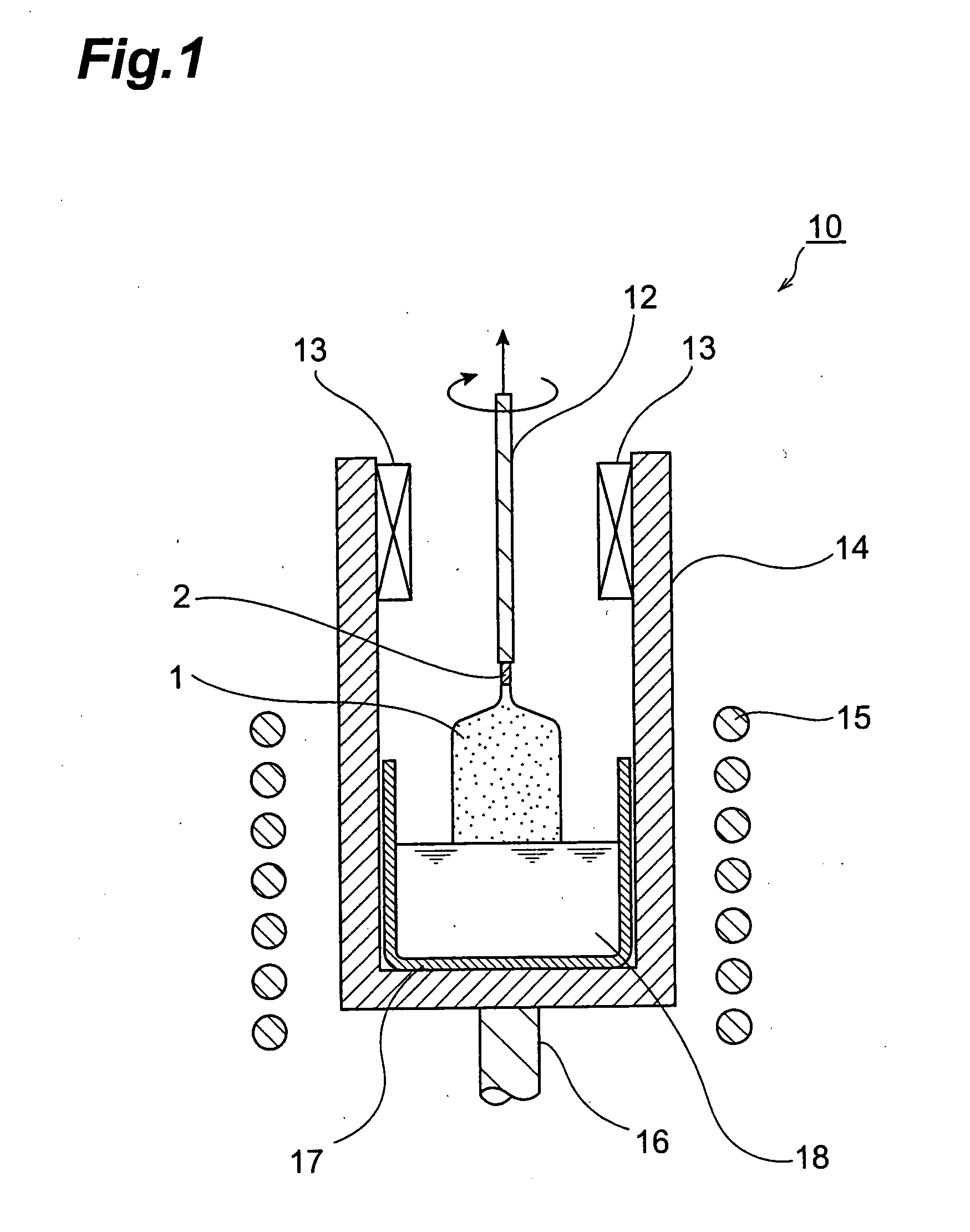
[0054] As materials, 20489.1 g of gadolinium oxide (Gd2O3 with a purity of 99.99 mass %), 3413.1 g of silicon dioxide (SiO2 with a purity of 99.99 mass %), 97.8 g of cerium oxide (CeO2 with a purity of 99.99 mass %), and 2.4 g of hafnium oxide (HfO2 with a purity of 99.99 mass %) were put into an Ir crucible having a diameter of 180 mm, a height of 180 mm, and a thickness of 3 mm, whereby 24002.4 g of their mixture were obtained. The mixture was subsequently heated in a high-frequency induction heating furnace to a temperature of 1950° C. or higher so as to be melted, whereby a melt liquid was obtained.

[0055] Next, the tip of a lifting rod having a seed crystal secured to its lower end was introduced into the melt liquid, so as to perform seeding. Subsequently, a single-crystal ingot having a neck diameter of 8 mm was raised at a lifting rate of 1 to 3 mm / h, so as to form a neck part. Then, a cone part (cylindrical part) was raised. Here, the raising of the cylindrical part was sta...


PUM

PropertyMeasurementUnit
thicknessaaaaaaaaaa
heightaaaaaaaaaa
diameteraaaaaaaaaa

Abstract

The present invention provides an inorganic scintillator including a matrix material comprising a metal oxide, and a luminescence center made of Ce contained in the matrix material, the inorganic scintillator being adapted to scintillate in response to a radiation; wherein the matrix material further comprises a dopant having a tetravalent ionization energy I [kJ·mol−1] satisfying the condition represented by the following expression (1):
3000≦I≦3500   (1)

Description

BACKGROUND OF THE INVENTION [0001] 1. Field of the Invention [0002] The present invention relates to an inorganic scintillator. [0003] 2. Related Background Art [0004] In the positron emission computed tomography (hereinafter referred to as “PET”), optical characteristics (wavelength conversion characteristics, etc.) of scintillators employed therein greatly influence imaging performances of the whole system, whereby an improvement in the optical characteristics of scintillators is one of the most important points in ameliorating the imaging performances of the whole system. Therefore, searches for scintillator materials which can construct scintillators having excellent optical characteristics, and developments for manufacturing techniques such as crystal growing techniques for putting these scintillators into practical use have vigorously been under way. In the field of high-energy physics, on the other hand, there have been demands for practically using scintillators which can ef...

Claims


Application Information

Patent Timeline
Patent Type & Authority Applications(United States)
IPC IPC(8): G01T1/20C01B33/12C09K11/00C09K11/08C09K11/77C09K11/78C09K11/79C30B29/34G01T1/202
CPCC09K11/7774C09K11/77742C09K11/08C09K11/0838C09K11/59C09K11/7706
Inventor KURASHIGE, KAZUHISAISHIBASHI, HIROYUKISUMIYA, KEIJISENGUTTUVAN, NACHIMUTHUYOSHIDA, KAZHUHIROSHIMURA, NAOAKI
Owner HITACHI CHEM CO LTD
Why Eureka
Try Eureka