Amplifying circuit with adjustable amplification and transmitter system comprising such an amplifying circuit

a technology of amplifier circuit and amplifier circuit, which is applied in the direction of amplifier modification to reduce non-linear distortion, gain control, gated amplifier, etc., can solve the problems of unavoidable problems, unadjustable radio-frequency amplifiers of this type, and high current drawn,

Inactive Publication Date: 2005-08-11
INFINEON TECH AG
View PDF8 Cites 29 Cited by
  • Summary
  • Abstract
  • Description
  • Claims
  • Application Information

AI Technical Summary

Benefits of technology

[0027] Instead of the exponentially graduated threshold values as comparison potentials for the comparators, it is also possible to use a linear graduation for the threshold values and to alter the weighting of the gain contributions by the individual differential amplifier cells accordingly, so that an exponential characteristic curve for the amplifier likewise results overall.
[0028] In general, the principle presented may be used to generate any desired characteristic curve, for example logarithmic, linear or exponential, for the output power as a function of the control voltage.
[0029] The present amplifier is particularly suitable for use in mobile radio transmitters with direct conversion of baseband to the radio-frequency level and is provided for use in equipment based on UMTS (Universal Mobile Telecommunications Standard) which operates using code division multiple access (CDMA).

Problems solved by technology

Adjustable radio-frequency amplifiers of this type are subject to great demands in terms of current drawn, efficiency, linearity, noise and chip area requirement.
The latter demand results in problems with crosstalk, and in radio-frequency engineering, particularly in unwanted break-through of carrier frequencies, self-mixing effects etc.
When amplifying radio-frequency signals, however, the inductance disadvantageously acts as an antenna or transformer, particularly in the GHz range, and thus presents an unavoidable problem as regards the crosstalk of signals through the alternating electromagnetic field on the integrated circuit onto other circuits.
A further problem is regulation of the power output from the amplifier.
It can be seen that the power output from the amplifier can be controlled only by intervening in the latter's supply of quiescent current, which would disadvantageously shift the amplifier's operating point accordingly.
With a relatively large gain range, however, this would bring about unwanted nonlinearities in the differential amplifier.
The most serious drawback of power regulation of this type is provided by the constant current drawn by the power amplifier.
The amplifier itself requires a constant power at every point of the characteristic curve, which significantly reduces the efficiency of the overall circuit when the output power is brought down.

Method used


Image

  • Amplifying circuit with adjustable amplification and transmitter system comprising such an amplifying circuit
  • Amplifying circuit with adjustable amplification and transmitter system comprising such an amplifying circuit
  • Amplifying circuit with adjustable amplification and transmitter system comprising such an amplifying circuit

Examples


Embodiment Construction

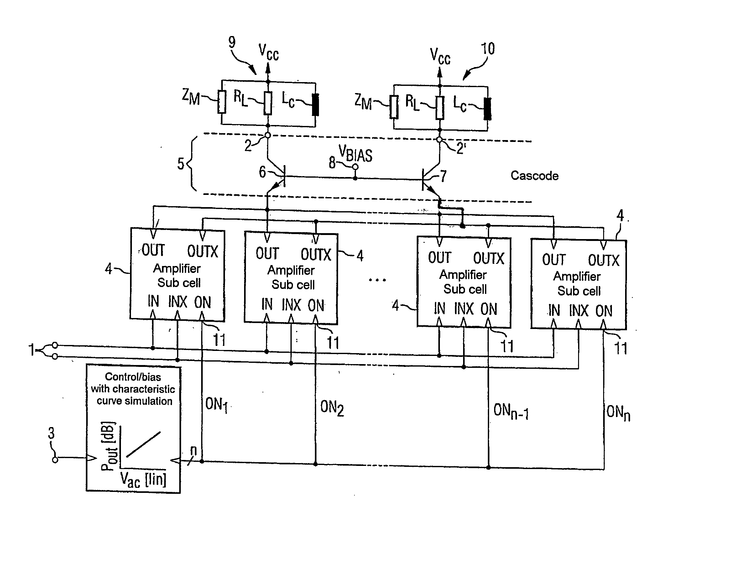
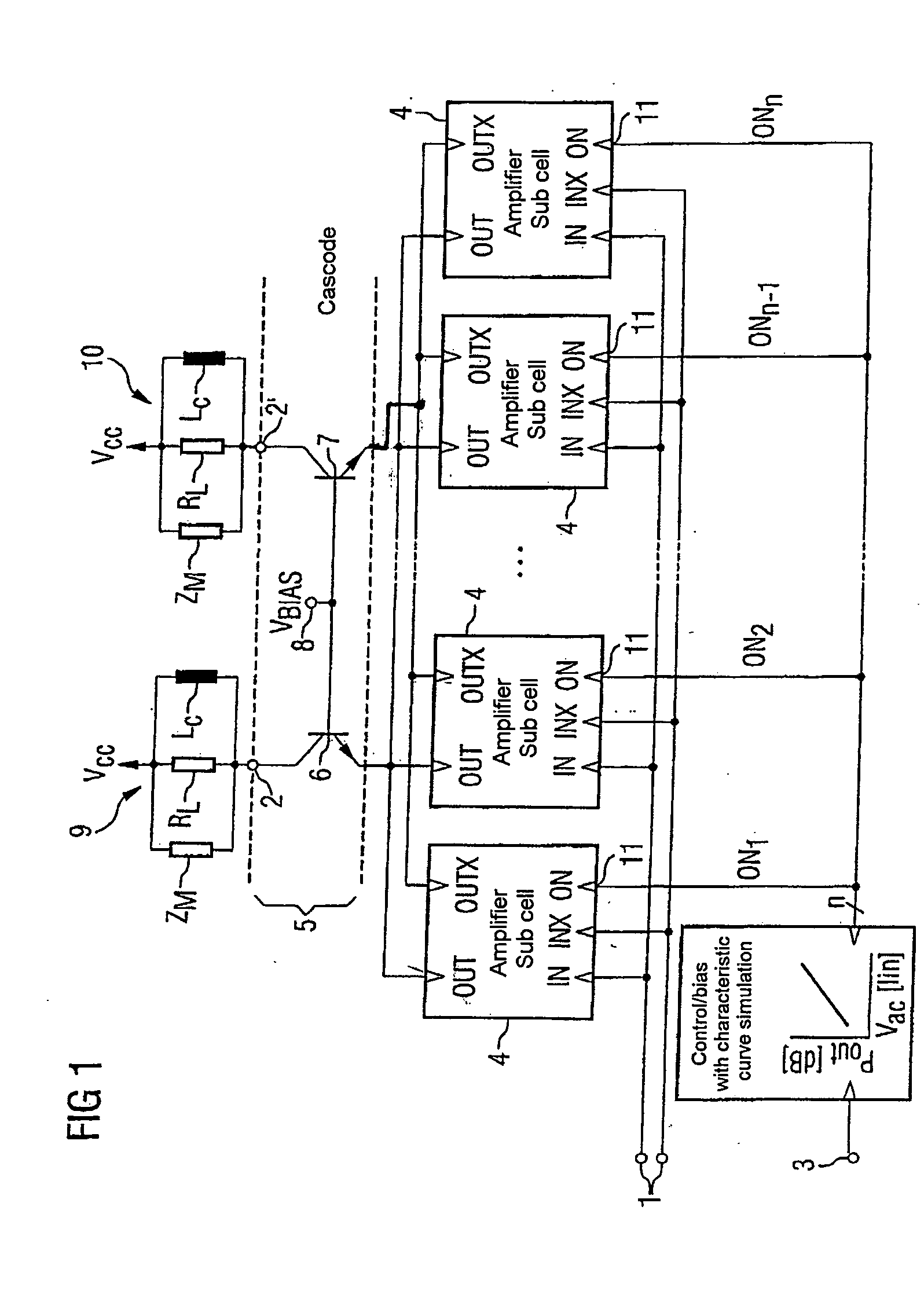
[0039]FIG. 1 shows an amplifier circuit with an adjustable gain value. This circuit has a useful-signal input 1 for supplying a differential useful signal which is in the form of an input terminal pair. The amplified useful signal can be derived at the output terminal pair 2, 2′ of the amplifier. A control input 3 may be used to supply a nominal signal for a desired gain value for the amplifier as a voltage signal. A plurality of differential amplifiers 4 connected to one another in a parallel circuit are connected to the input 1 by their respective input terminal pairs. Their output terminal pairs, which are likewise of differential design and are connected to one another, have a common cascode stage 5 connected to them which comprise two cascode transistors 6, 7. The cascode transistors 6, 7 are produced using bipolar circuitry and have their base connections connected to one another and to a bias voltage input 8. The emitter output pair is connected to the output terminal pairs o...


PUM


Abstract

The invention is directed to an amplifier circuit with adjustable gain which includes a plurality of parallel-connected differential amplifiers connected to a common cascode stage. An actuation unit is used to activate the differential amplifiers independently of one another on the basis of an applied control signal. The principle described makes it possible to dispense with inductances in the differential amplifier and hence to reduce unwanted crosstalk, while having a high linearity. Secondly, the amplifier's drawn current matches the respective output power which can be tapped off. Overall, the principle described is particularly suitable for use in UMTS mobile radios.

Description

REFERENCE TO RELATED APPLICATION [0001] This application is a continuation of PCT / DE03 / 02286, which was not published in English, that claims the benefit of the priority date of German Patent Application No. DE 102 31 181.1, filed on Jul. 10, 2002, the contents of which are herein incorporated by reference in their entirety.FIELD OF THE INVENTION [0002] The present invention relates to an amplifier circuit with adjustable gain and to a transmission arrangement with the amplifier circuit. BACKGROUND OF THE INVENTION [0003] In radio-frequency engineering, “RF power amplifiers” are normally used on the output side in the transmission path. In the case of third-generation mobile radios, for example, which are designed for UMTS (Universal Mobile Telecommunications Standard), “W-CDMA” (Wide-Band Code Division Multiple Access) signals with a bandwidth of two megahertz need to be amplified over an exponential characteristic curve on a carrier-frequency level of approximately 2 Ghz. An expon...

Claims


Application Information

Patent Timeline
Patent Type & Authority Applications(United States)
IPC IPC(8): H03G3/10H03F1/06H03F1/32H03F3/24H03F3/45H03F3/68H03F3/72H04B1/04
CPCH03F1/0205H03F2203/7203H03F3/24H03F3/45188H03F3/68H03F3/72H03F2200/336H03F2200/78H03F2203/45244H03F2203/45268H03F2203/45541H03F2203/45544H03F2203/45564H03F2203/45618H03F2203/45638H03F2203/45702H03F1/32
Inventor HEIGELMAYER, BERNHARDPRETL, HARALD
Owner INFINEON TECH AG
Why Eureka
Try Eureka