

Optical combiner device
- Summary
- Abstract
- Description
- Claims
- Application Information
AI Technical Summary
Benefits of technology
Problems solved by technology
Method used
Image

Examples
first embodiment
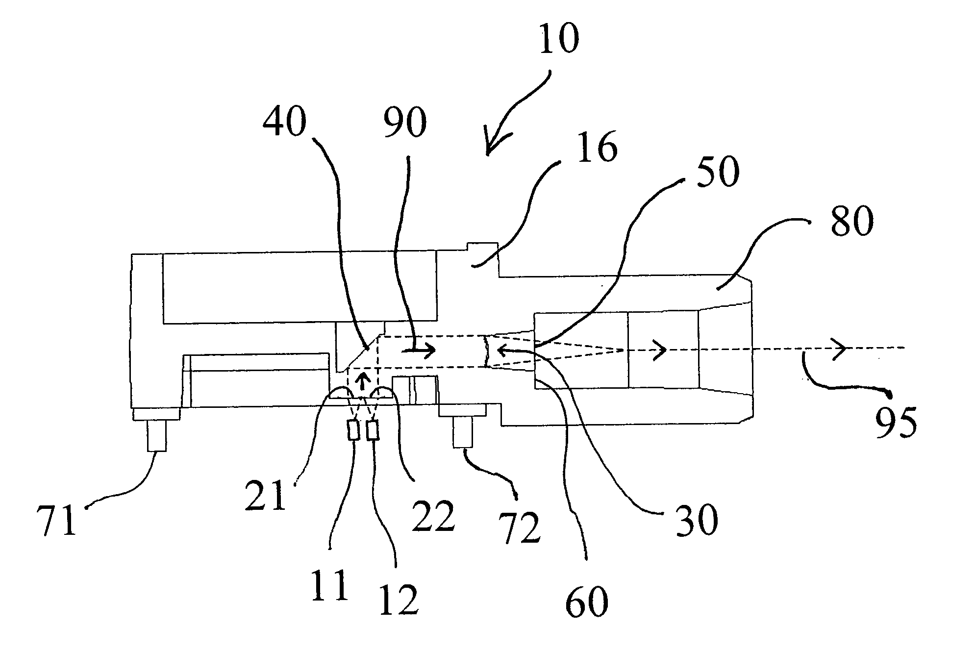
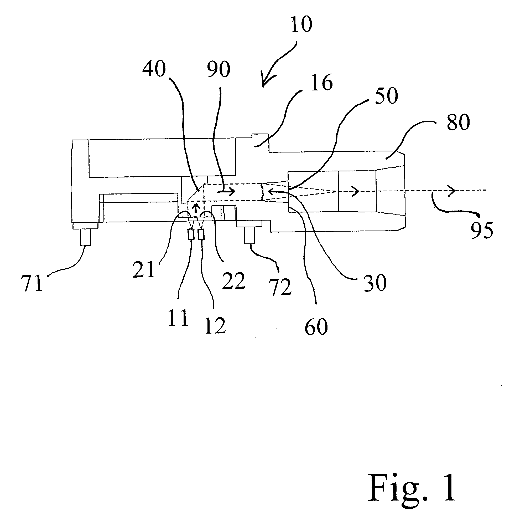
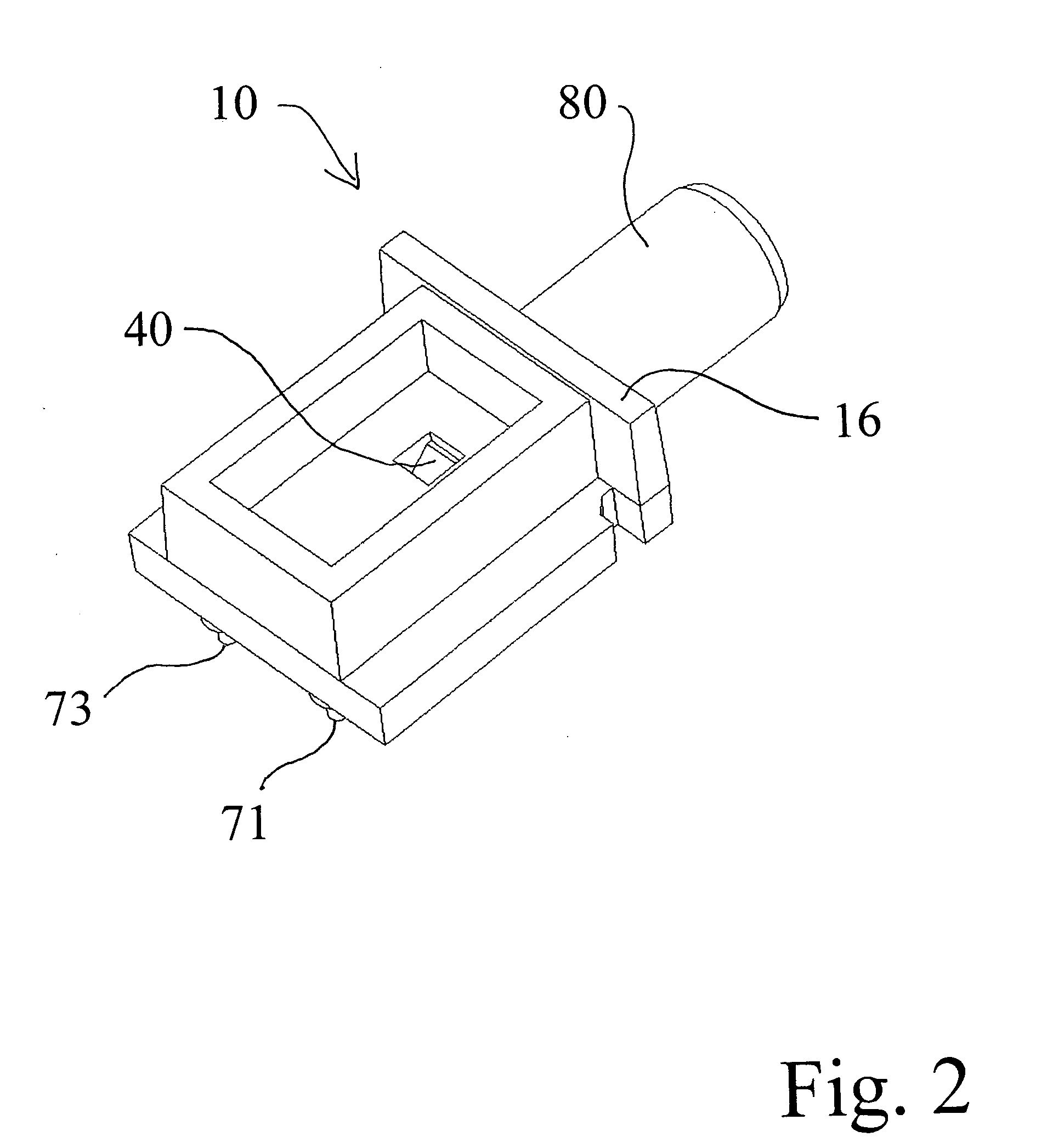
[0025]FIGS. 1-4 show an optical combiner 10 that illustrates the present invention. The combiner 10 in this embodiment includes four spaced apart input collimating lenses 21,22, 23,24 and output focusing lens 30. Lasers 11,12 are located at the focal points of the input lenses and the light is collimated, reflected off a prism 40 and focused by the focusing lens 30 onto a spot at which a single optical fiber (not shown) is stopped by fiber stop or seat 60 formed in ferrule 80. Pins 71,72,73,74 are located to aid in affixing the combiner device 10 to the support (not shown) for the lasers. The integrated ferrule 80 enables one to place an output fiber optic cable into the pre-aligned connector.
[0026] This combiner device has the ability to combine individual light signals into an optical path 90 that can be directed towards an optical fiber (not shown for clarity). Matching the NA of the larger focusing lens 30 and the NA of the fiber (not shown) inserted into ferrule 80, seated at t...
second embodiment
[0030]FIGS. 5 and 6 show the invention 110 which does not include a prism for translating the optical beams from one axis to another. This particular embodiment is beneficial for mating to a standard “TO” style laser chip package. Similar to the embodiment described in FIGS. 1-4, the embodiment shown here utilizes a two-dimensional array of four lenses 121,122,123,124 for collimating the input light signals from a two-dimensional, two by two, array of lasers (not shown), a single focusing lens 130, and a fiber connector 180 that allows one to place a fiber optic cable into the pre-aligned connector.
third embodiment
[0031]FIGS. 7, 8 and 9 illustrate the invention. The combiner is shown generally as 210 and includes a circular array of four lasers 211,212,213 and 214. Each laser 211-214 has a different output wavelength. Each laser is mounted to a support 215. The lasers 211-214 are co-planar and the output beam of each of the lasers 211-214 is directed towards the center of the array. At the center of the array is a coupling optic 216 formed of a single monolithic optical block. Four collimating lenses (only two of which 221 and 222 are visible) are formed in the four side walls 231,232,233 and 234, respectively, of the module or coupling block 216. The focusing lens 250 is formed on the top surface of the module 216. The surface of focusing lens 250 is smooth and includes four pie-shaped radial quadrants 251-254. Each of the quadrants 251-254 transmits a separate output beam of the lasers 211-214, respectively.
[0032] As shown best in FIG. 8, the bottom surface 240 of module 216 is recessed wit...
PUM
 Abstract
Description
Claims
Application Information