Variable low intensity infrared heater

a low-intensity infrared heater and variable technology, applied in the direction of combustion types, domestic stoves or ranges, combustion using lumps and pulverulent fuel, etc., can solve the problems of low combustion efficiency, difficult control of heating levels, constant blower speed

Active Publication Date: 2005-08-11
SOLARONICS
View PDF32 Cites 31 Cited by
  • Summary
  • Abstract
  • Description
  • Claims
  • Application Information

AI Technical Summary

Benefits of technology

[0013] According to a further feature of the invention methodology the gas flow control assembly has either of two valves or two regulators operating in parallel and the method includes the step of opening one valve or regulator and closing one valve or regulator when the regulator is operating at the low level and opening both valves or regulators when the gas

Problems solved by technology

These low intensity infrared heaters generally operate at full capacity when not in an off condition with the result that the burner constantly cycles between its on condition and its off condition, thus making it difficult to control heating levels.
The problem with this system is that even though the gas pressure, and therefore the gas volume, is varied between the two stages, the blower speed is constant.
Therefore there is

Method used


Image

  • Variable low intensity infrared heater
  • Variable low intensity infrared heater
  • Variable low intensity infrared heater

Examples


Embodiment Construction

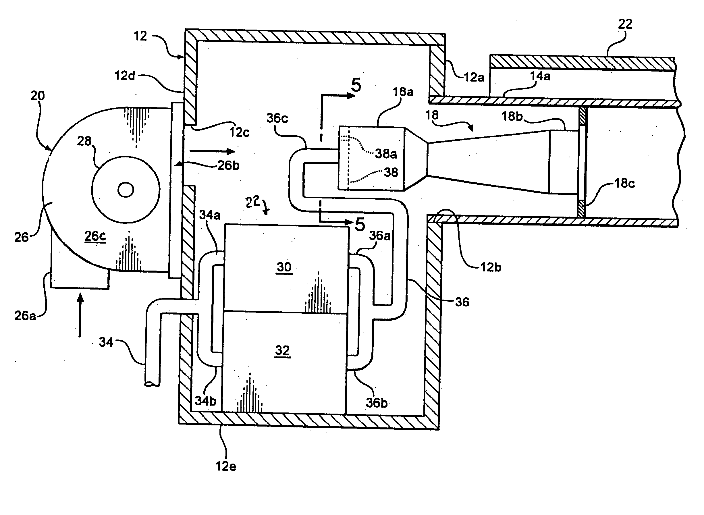
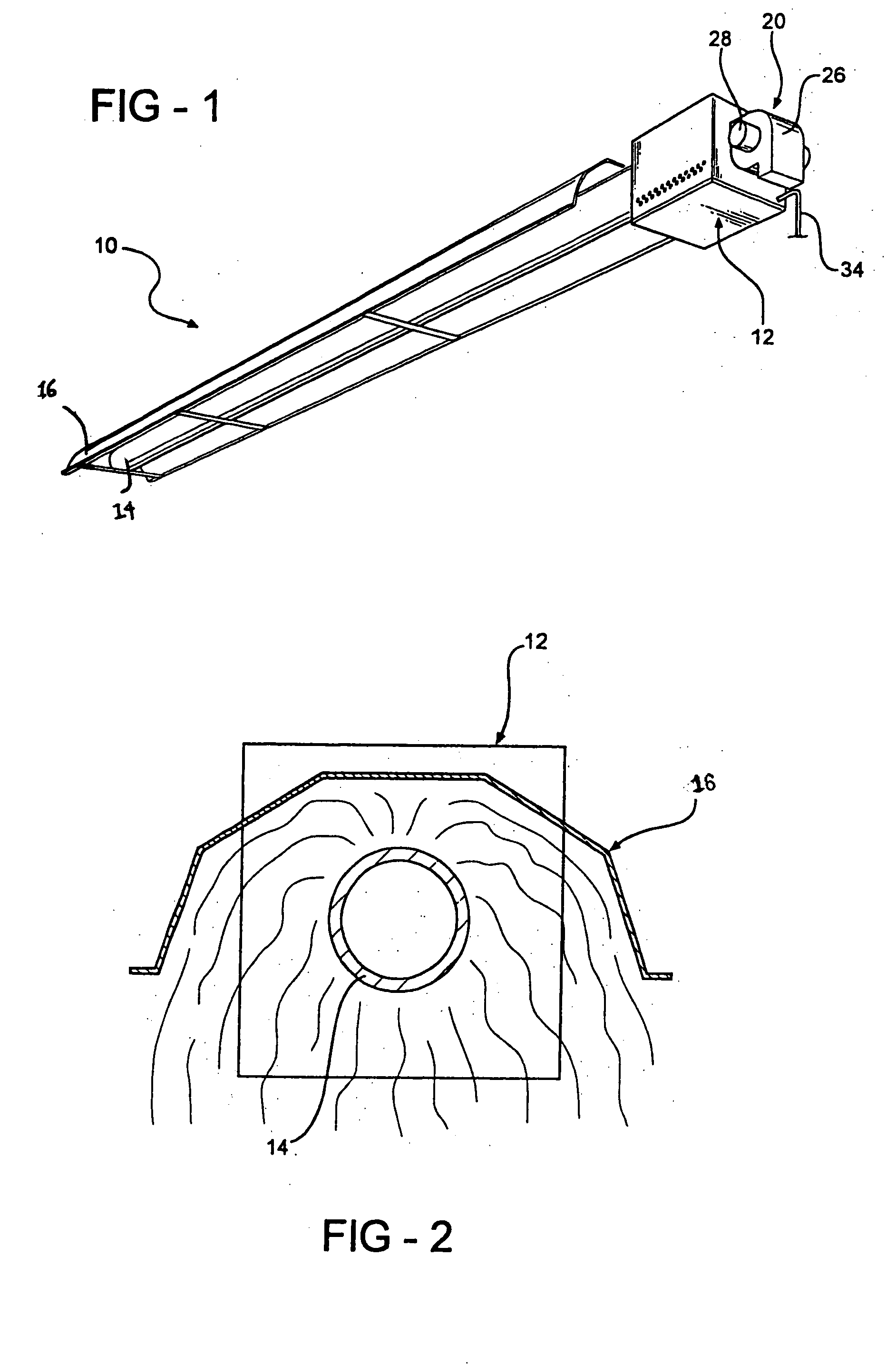
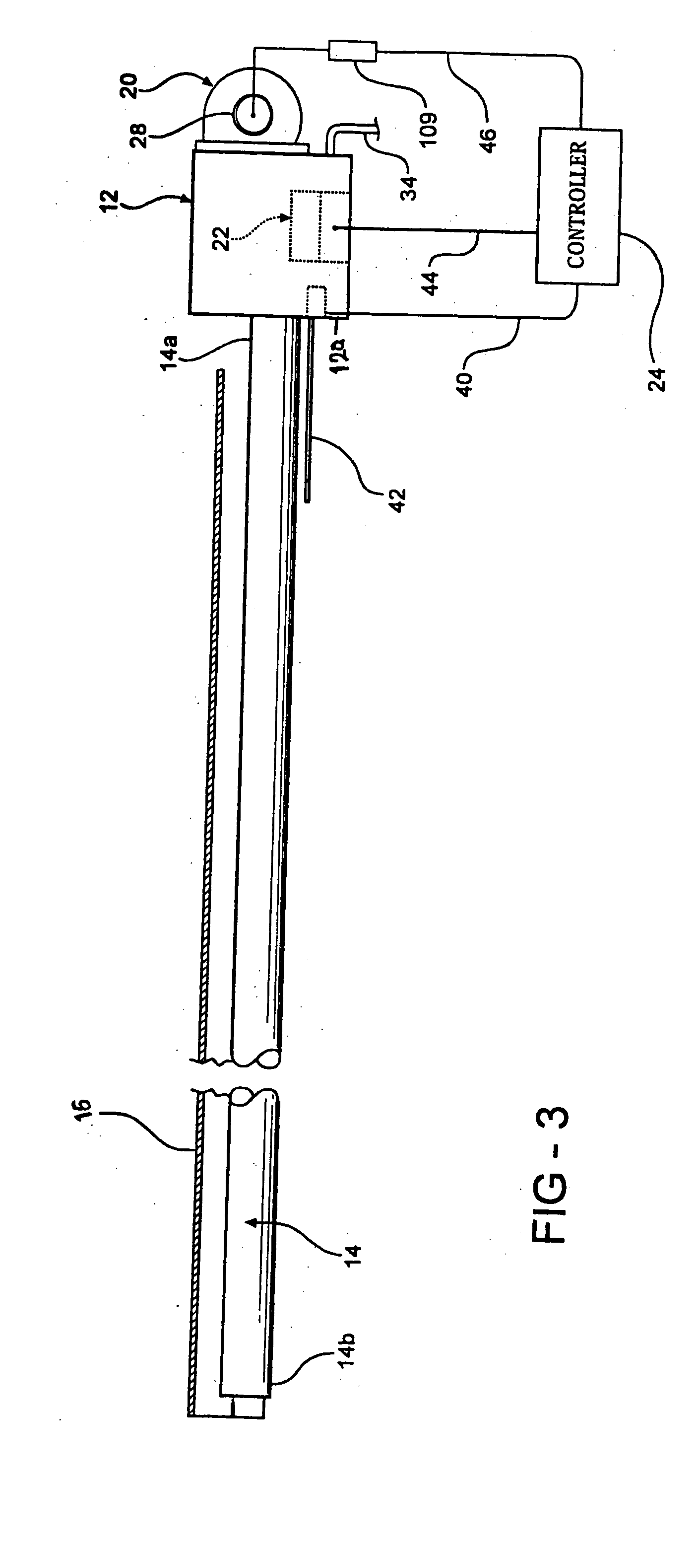
[0023] The infrared heater 10 of the invention, broadly considered, includes a housing 12, a radiant tube 14, a reflector 16, a burner 18 (shown only in FIG. 4), a blower 20, a gas flow control assembly 22, and a controller 24 (shown only in FIG. 3).

[0024] Housing 12 has a box like sheet metal configuration.

[0025] Radiant tube 14 is elongated and includes an inlet end 14a secured to a front wall 12a of housing 12, in communication with a wall aperture 12b as shown in detail in FIG. 4. Radiant tube 14 also includes an exhaust end 14b as shown in FIG. 3.

[0026] Reflector 16 has an inverted U configuration in cross-section, is suitably supported in spaced overlying relation to tube 14, and is generally coextensive with tube 14.

[0027] As shown in FIGS. 4 and 5, burner 18 is elongated and generally tubular, has a venturi configuration, and includes an inlet end 18a positioned in housing 12 proximate wall 12a and an outlet end 18b positioned in the inlet end 14a of tube 14 and centered...


PUM


Abstract

A radiant heater including a burner having an inlet for receiving an air and gas mixture and an exhaust for emitting exhaust gases generated by combustion of the air and gas mixture within the burner, an elongated radiant heating tube having an inlet for receiving the exhaust gases emitted by the burner, a gas flow control assembly for controlling the flow of gas to the burner, and a blower for controlling the flow of air to the burner. The blower comprises a two-stage blower including a motor having a low winding corresponding to a low blower speed and a high winding corresponding to a high blower speed. The gas flow control assembly comprises a two-stage regulator or two stage two-stage valve having a low setting for delivering a low gas flow to the burner and a high setting for delivering a high gas flow to the burner.

Description

FIELD OF THE INVENTION [0001] This invention relates to an apparatus and method for heating an enclosed space with a variable low intensity infrared heater. BACKGROUND OF THE INVENTION [0002] Gas fired infrared heaters typically are used in large industrial settings. A gas heater burns natural gas, propane, or similar combustible gases and the combustion by-products or exhaust gases are passed through a radiant heating tube which becomes hot and radiates energy waves therefrom Reflectors are often used to reflect the energy waves toward the desired location usually toward the floor where the infrared energy waves are converted into heat. These low intensity infrared heaters generally operate at full capacity when not in an off condition with the result that the burner constantly cycles between its on condition and its off condition, thus making it difficult to control heating levels. [0003] There have been some attempts to create a two-stage heater by utilizing a single gas flow con...

Claims


Application Information

Patent Timeline
IPC IPC(8): F23C3/00F23D14/12F24C3/12
CPCF23C3/002F23D14/12F23D2900/14121F24C3/122F23N2033/08F23N2035/18F23N2037/10F23N2025/12F23N2225/12F23N2237/10F23N2235/18F23N2233/08F23D14/151
Inventor AHMADY, FARSHID
Owner SOLARONICS
Why Eureka
Try Eureka