Agricultural machine with energy reservoir for overcoming peak loads

Active Publication Date: 2005-08-18
CLAAS SELBSTFAHRENDE ERNTEMASCHINEN GMBH
View PDF10 Cites 23 Cited by
  • Summary
  • Abstract
  • Description
  • Claims
  • Application Information

AI Technical Summary

Benefits of technology

[0011] Since the at least one electric drive unit is associated with the at least one energy producer and has means for controlling an energy supply of the at least one working unit according to the energy needs thereof, additional energy in the drive system can be supplied. Since the energy storage occurs in the drive system, especially during power fluctuations, such as rotation speed fluctuations of the chopper drum of the self-powered forager harvester, the agricultural harvesting machine can operate at a constant power level. For this purpose the constantly varying power needs of the harvesting machine are compared with the supply of additional energy. Moreover the fluctuations of the various loads occurring are reduced because of the reductions in the rotation speed fluctuations achieved by the features of the invention.
[0013] Because the at least one electric drive is turned on and off according to the energy requirements of the at least one other energy producer, the rotation speeds of the working units driven by the energy producer can be kept constant. Hereby the energy producer, which can be designed as an internal combustion engine, is less heavily loaded. Also fuel is saved and the driver is relieved since the operation can be continued unchanged at a constant travel speed.
[0015] When the control of the energy requirements can be adjusted according to the energy requirements, the driver of the agricultural machine can exactly establish the threshold value for the energy supplied and thus perform an adjustment to the actual harvest conditions in order to optimize the burden on the entire agricultural machine.

Problems solved by technology

Agricultural machines are subjected to considerable loads during harvesting.
Especially the motor speed of agricultural machines strongly fluctuates because of non-uniform crop conditions.
It is problematic that frequently this action is not performed quickly enough, so that the working units are clogged or the crop quality is poor.
The energy consumption itself remains high and unchanged and is not adjusted to the actual requirements of the agricultural machine at any point.
Improved energy consumption is not achieved by the arrangements of the parts.

Method used


Image

  • Agricultural machine with energy reservoir for overcoming peak loads
  • Agricultural machine with energy reservoir for overcoming peak loads
  • Agricultural machine with energy reservoir for overcoming peak loads

Examples


Embodiment Construction

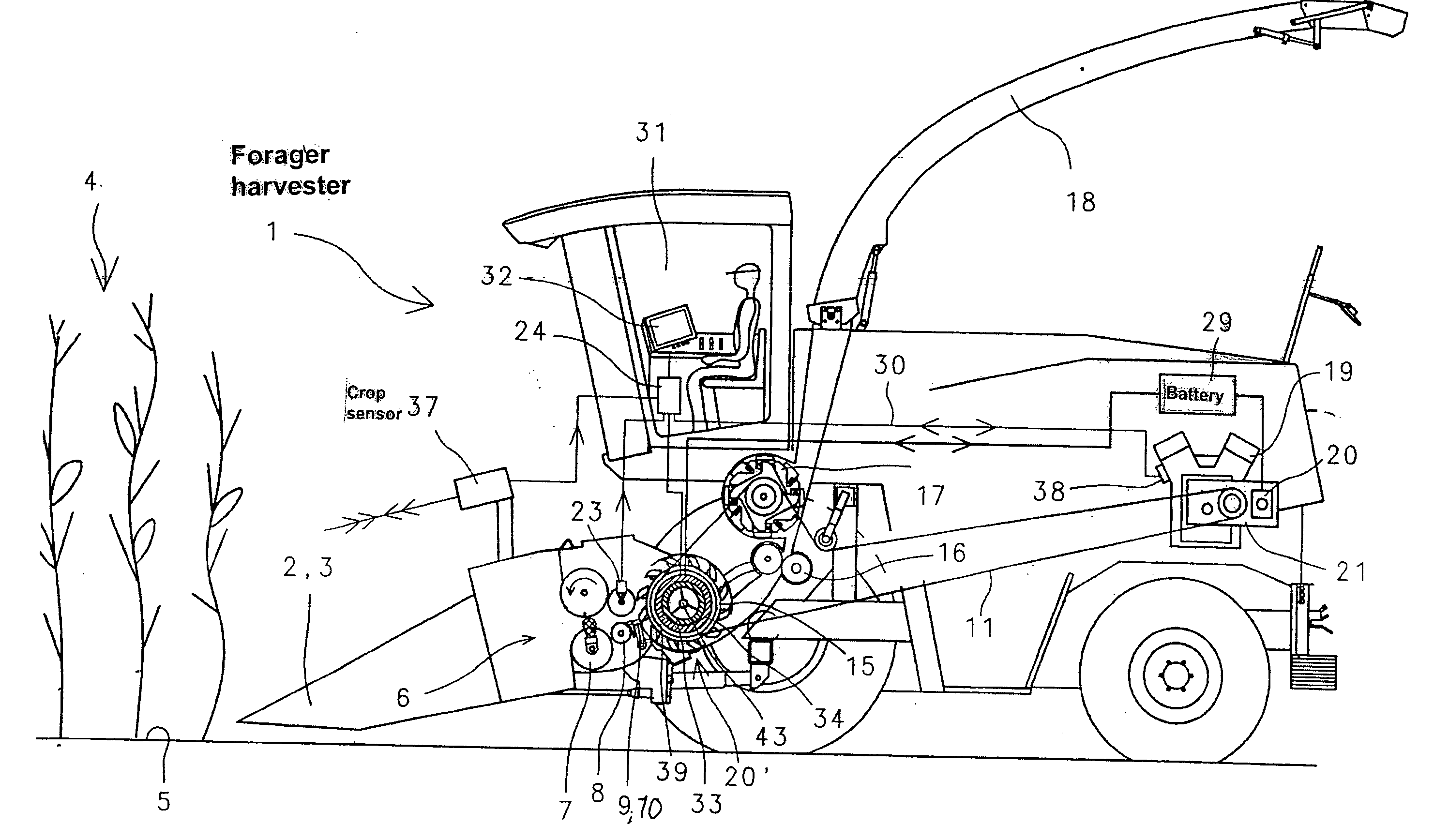
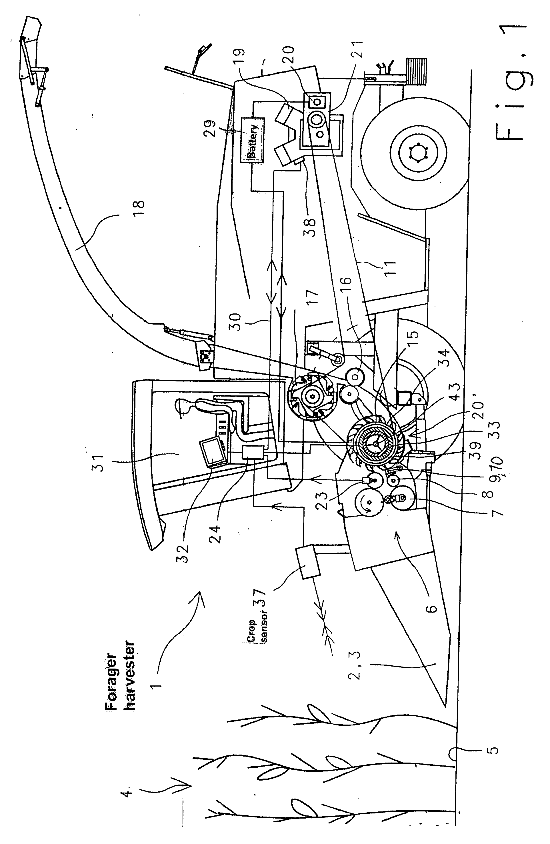
[0022]FIG. 1 is a schematic side view of a self-powered forager harvester according to the invention.

[0023] The front attachment 2 mounted on the front end of the forager harvester 1, which is primarily formed as a corn header 3, is replaceable according to the respective type of crop 4 and takes in the crop 4 from the ground 5, chops it up and supplies it to the connected working units 7, 8, 15, 16 and 17.

[0024] A crop sensor 37 for detecting the crop condition without contacting the crop is associated with the front attachment 2. The sensor 37 detects how much of the crop 4 is fed into the working units and changes the travel speed of the self-propelled forager harvester, the rotation speeds of the working units 7, 8, 15, 16, 17 or the rotation speed of the engine 19 in a generally known manner.

[0025] The front attachment 2, which has a width of several meters, conducts the crop 4 that it takes in into a feeder region 6. The crop 4 is taken through the feeder region 6 by a firs...


PUM


Abstract

The agricultural machine has at least one energy producer (19); at least one energy storage device; at least one working unit (2, 4, 7, 8, 15, 16, 17) driven by the at least one energy producer (19) and at least one electric drive unit (20) associated with the at least one energy producer (19). The at least one electric drive unit (20) controls the energy supply of the at least one working unit (2, 4, 7, 8, 15, 16, 17) according to energy requirements of the at least one working unit (2, 4, 7, 8, 15, 16, 17) since it supplies energy to or takes it from the at least one energy storage device (29) as needed.

Description

BACKGROUND OF THE INVENTION [0001] 1. Field of the Invention [0002] The present invention relates to an agricultural machine comprising at least one energy producing device, which drives at least one working unit of the agricultural machine and at least one energy source. [0003] 2. Description of the Related Art [0004] Agricultural machines are subjected to considerable loads during harvesting. All working units, such as cutter bars, chopper drums or conditioning rollers, of a self-powered forager harvester are greatly loaded by the crop to be harvested. The rotation speeds of the working units must be kept constant in order to guarantee unobjectionable processing of the crop. Especially the motor speed of agricultural machines strongly fluctuates because of non-uniform crop conditions. Thus the engine power requirements fluctuate depending on the amount of the crop fed to the working units. This has the result that the engine is very greatly loaded with very thick crop conditions a...

Claims


Application Information

Patent Timeline
IPC IPC(8): A01D69/00A01D69/02A01F29/14
CPCA01D43/085Y10S180/90A01D69/025B60L2200/40B60L50/15Y02T10/7072Y02T10/70
Inventor DEPPE, MARKUS
Owner CLAAS SELBSTFAHRENDE ERNTEMASCHINEN GMBH
Why Eureka
Try Eureka