System and method of operating an internal combustion engine

a technology of internal combustion engine and system, applied in the direction of machines/engines, electric control, speed sensing governors, etc., can solve the problems of high life cycle cost, increase the cost of manufacturing the engine, increase the cost of fuel consumption, etc., and achieve constant engine power level, increase the effect of fuel injection and reducing the normal engine speed

Active Publication Date: 2018-10-09
GE GLOBAL SOURCING LLC
View PDF27 Cites 0 Cited by
  • Summary
  • Abstract
  • Description
  • Claims
  • Application Information

AI Technical Summary

Benefits of technology

[0022]The optimizing of the engine speed at each engine power setting includes reducing a normal engine speed at the corresponding engine power setting while maintaining constant engine power level by increasing the fuel injection per cycle for increasing engine torque such that power is maintained at the same level. In one embodiment, an injection pressure may also be increased for increasing fuel injection per cycle to increase the engine torque. The reduction of the normal engine speed at each engine power setting is based on meeting a threshold limit of multiple operating parameters including peak cylinder pressures and engine shaft bearing loads. Further, the reduction of the normal engine speed at each engine power setting is based on an air-handling system requirement of an oxygen-to-fuel ratio (OFR) of at least a value greater than the threshold at the respective engine power. The oxygen-to-fuel ratio (OFR) is defined as the ratio of a total intake of oxygen mass flow to a fuel mass flow. It is to be noted that speed reduction may be higher at lower engine power settings (lower notches) for reducing particulate matter emissions.

Problems solved by technology

However, the use of aftertreatment systems may increase the cost of manufacturing the engines and fuel consumption leading to high life cycle cost.

Method used


Image

  • System and method of operating an internal combustion engine
  • System and method of operating an internal combustion engine
  • System and method of operating an internal combustion engine

Examples


Embodiment Construction

[0012]When introducing elements of various embodiments of the present invention, the articles “a,”“an,”“the,” and “said” are intended to mean that there are one or more of the elements. The terms “comprising,”“including,” and “having” are intended to be inclusive and mean that there may be additional elements other than the listed elements. Any examples of operating parameters are not exclusive of other parameters of the disclosed embodiments.

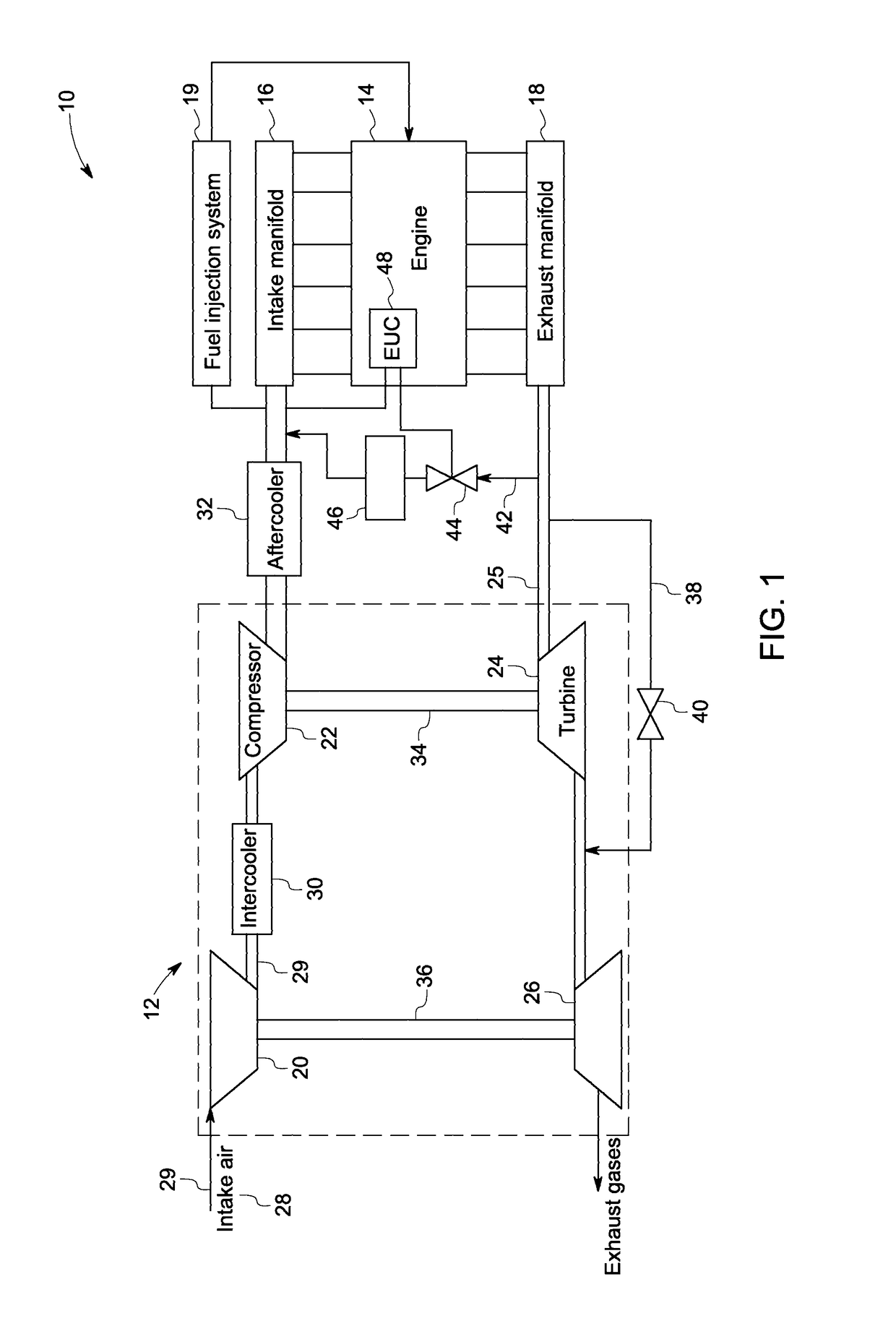
[0013]FIG. 1 is a schematic view of a system 10 having a turbocharger unit 12 in accordance with an embodiment of the present invention. The turbocharged unit 12 includes a two staged turbocharger and a compression-ignition engine, e.g., a diesel engine 14. In one embodiment, the system 10 may include a single staged turbocharger. The engine 14 includes a plurality of combustion cylinders. A piston (not shown) is slidably disposed in each cylinder and reciprocates between a top dead center and a bottom dead center position. It should be noted h...


PUM


Abstract

A method of operating an internal combustion engine is provided. The method includes combusting a mixture of fresh air and fuel within multiple cylinders. The method also includes directing a first portion of exhaust gases into a first-stage turbine and a second-stage turbine of a turbocharger for expanding the exhaust gases, directing a second portion of exhaust gases from the exhaust manifold via an exhaust channel bypassing the first-stage turbine and recirculating a third portion of exhaust gases into an intake manifold after mixing with fresh air. The method includes controlling at least one of: reducing a normal engine speed at each engine power setting while maintaining constant engine power level by increasing a fuel injection per cycle; concurrently increasing a flow rate of the third portion of exhaust gas during recirculation; and advancing a fuel injection timing for reducing emission levels that meets Tier 4 requirements.

Description

BACKGROUND[0001]The embodiments of the present invention relate generally to a system and method of operating an engine and, more specifically, to a system and method for controlling exhaust emissions of an engine.[0002]Compression-ignition engines, such as diesel engines, operate by directly injecting a fuel (e.g., diesel fuel) into compressed air in one or more piston-cylinder assemblies, such that the heat of the compressed air ignites the fuel-air mixture. Compression-ignition engines may also include a glow plug to provide heat to ensure ignition. The direct fuel injection atomizes the fuel into droplets, which evaporate and mix with the compressed air in the combustion chambers of the piston-cylinder assemblies. Typically, compression-ignition engines operate at a relatively higher compression ratio than spark ignition engines. The compression ratio directly affects the engine performance, efficiency, exhaust pollutants, and other engine characteristics. In addition, the fuel-...

Claims


Application Information

Patent Timeline
Patent Type & Authority Patents(United States)
IPC IPC(8): F02B3/00F02D43/04F02B37/22F02B37/00F02B37/013F02B37/16F02B37/18F02D41/00F02M26/08F02M26/10F02B29/04F02D31/00F02D41/40F02D41/14F02M26/23
CPCF02D43/04F02B37/013F02B37/16F02B37/18F02B37/22F02D41/005F02D41/0007F02D41/1461F02D41/401F02M26/08F02M26/10F02B37/004Y02T10/47F01N2560/026F02B29/0412F02D31/001F02D41/144F02D41/1454F02D41/40F02D2041/001F02D2250/18F02D2250/36F02D2250/38F02M26/23Y02T10/142Y02T10/144Y02T10/44Y02T10/12Y02T10/40
Inventor LAVERTU, THOMAS MICHAELKLINGBEIL, ADAM EDGARPRIMUS, ROY JAMESAKINYEMI, OMOWOLEOLA CHUKWUEMEKAGUMMADAVELLI, VENU GOPALRECORD, BARRY ALLENYAGER, JAMES HENRY
Owner GE GLOBAL SOURCING LLC
Why Eureka
Try Eureka