Dynamically modifiable polymer coatings and devices

a technology of dynamic modification and polymer coating, applied in the direction of photosensitive materials, instruments, vessel construction, etc., can solve the problems of increasing fuel consumption by up to 30-40%, reducing the range, speed and maneuverability of naval vessels, and affecting the safety of personnel

Active Publication Date: 2005-08-18
UNIV OF FLORIDA RES FOUNDATION INC
View PDF6 Cites 79 Cited by
  • Summary
  • Abstract
  • Description
  • Claims
  • Application Information

AI Technical Summary

Benefits of technology

[0015] A power supply supplies a dynamic electrical signal to the polymeric layer, wherein a contact angle of the polymeric layer substantially increases or decreases upon at least one of oxidation and reduction responsive to the dynamic signal. The polymer layer can also substantially expand or contract in at least one dimension (e.g. height, or width) upon at least one of oxidation and reduction. The subsurface of the boat or ship can be a metal or metal alloy (e.g. steel), wherein one terminal of the power supply is electrically connected to the subsurface of the boat or ship.
[0016] In one embodiment, the polymer layer is a patterned polymer layer, such as pattern of electrically isolated features. In this embodiment, the system can include a patterned electrode layer beneath the polymeric layer, where the electrode pattern is interdigitated and aligned with the features. The patterned polymer can include a plurality of microscale or nanoscale features. The plurality of features preferably provide a roughness factor (R) of at least 2, and

Problems solved by technology

Biofouling is estimated to cost the US Navy alone over $1 billion per year by increasing the hydrodynamic drag of naval vessels.
This in turn decreases the range, speed, and maneuverability of naval vessels and increases the fuel consumption by up to 30-40%.
Thus, biofouling weakens the national defense.
Moreover, biofouling is also a major economical burden on commercial shipping, recreational craft, as well as civil structures, bridges, and power generating facilities.
Any substrate in regular contact with water is likely to become fouled.
No surface has been found that is completely resistant to fouling.
Due to the vast var

Method used


Image

  • Dynamically modifiable polymer coatings and devices
  • Dynamically modifiable polymer coatings and devices
  • Dynamically modifiable polymer coatings and devices

Examples


examples

[0084] It should be understood that the example and embodiments described herein are for illustrative purposes only and that various modifications or changes in light thereof will be suggested to persons skilled in the art and are to be included within the spirit and purview of this application. The invention can take other specific forms without departing from the spirit or essential attributes thereof.

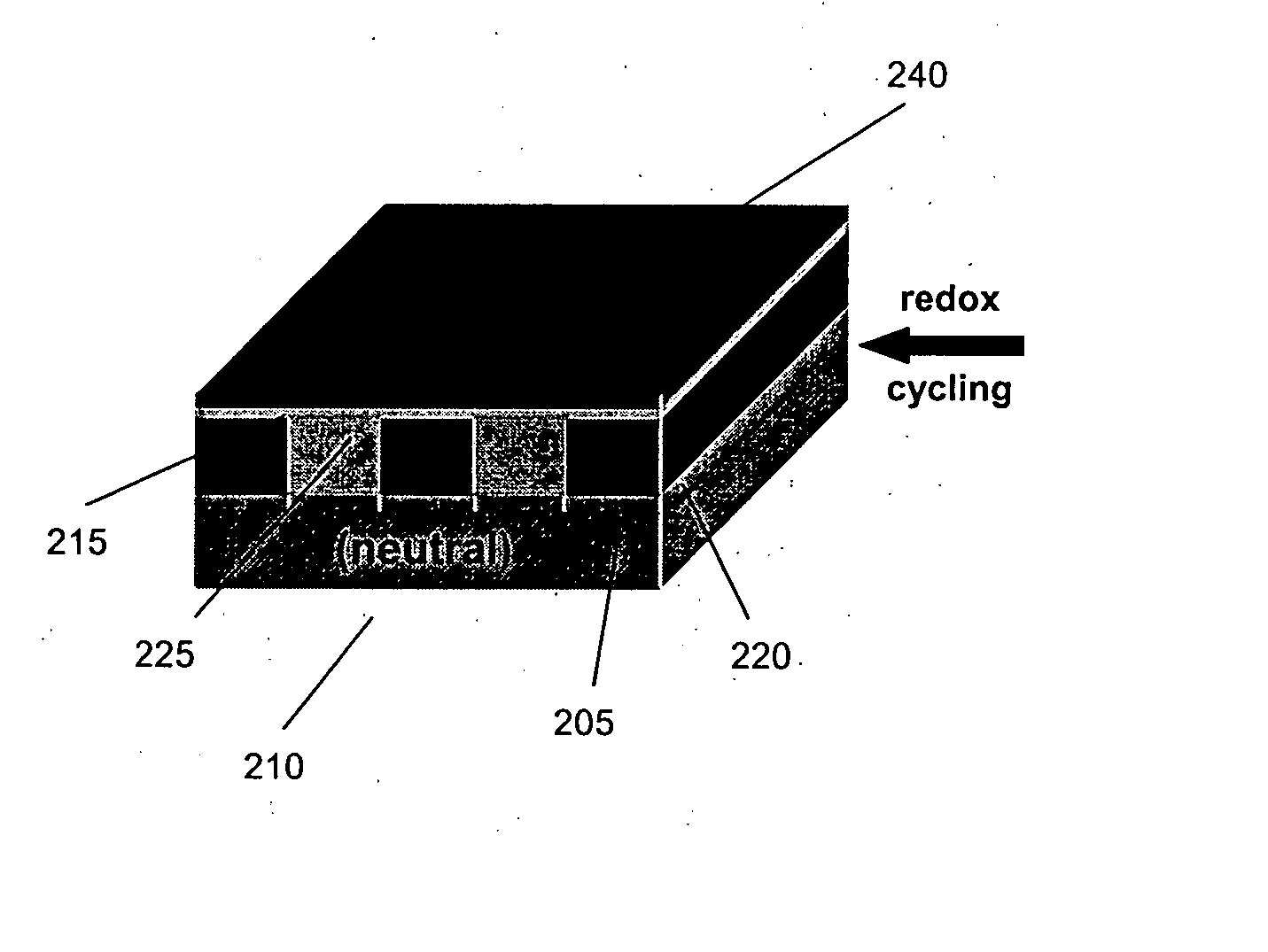
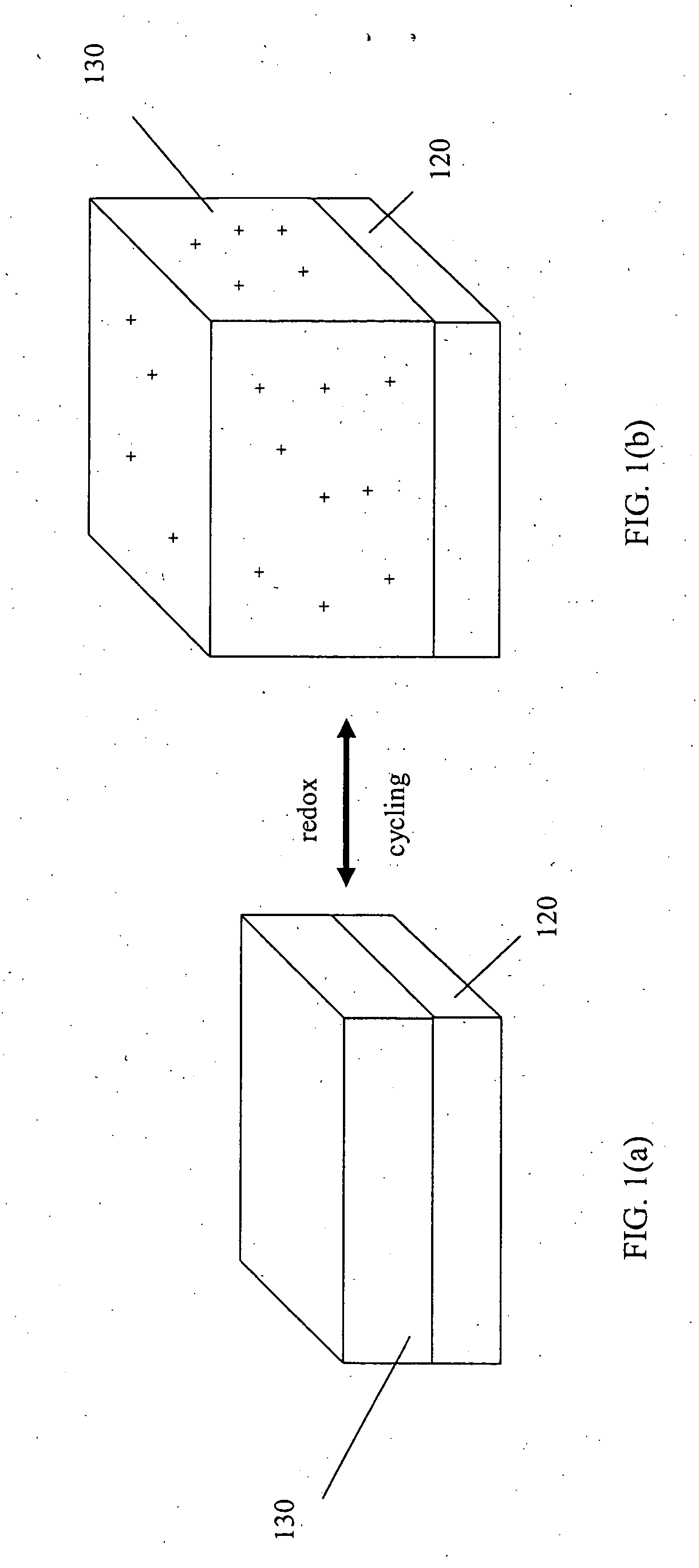
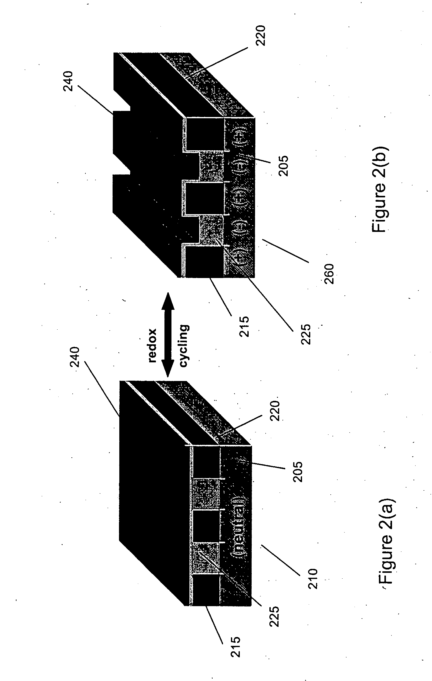
Polypyrrole (PPy) Surface Modified PDMSe

[0085] Surface modified PDMSe samples were prepared by soaking four PDMSe films in a 0.1 M Fe(III)Cl3 (oxidizer), NaClO4 (dopant) solution in ethanol for about 70 hrs. Ethanol is a good solvent for inorganic salts but is a poor solvent for silicone. This results in incorporation of the oxidant and dopant into only the surface layer of the PDMSe samples. PDMSe films were removed from the solutions and allowed to dry (evaporation of ethanol). The samples were then rinsed with distilled water (DI H2O) to remove any inorganic salts laying direct...


PUM

PropertyMeasurementUnit
Lengthaaaaaaaaaa
Electrical conductivityaaaaaaaaaa
Poweraaaaaaaaaa

Abstract

A dynamic coating includes at least one polymeric layer for attachment to a surface. The polymeric layer includes at least one electrically conducting polymer including layer, wherein under influence of a dynamic signal applied to the polymeric layer, a contact angle of the polymeric layer dynamically and substantially increases or decreases upon oxidation or reduction of the polymer. The polymeric layer can also expand or contract upon oxidation or reduction. The coating can be used for a variety of applications including a non-toxic biofouling preventative system and for forming low voltage electrowetting pumps.

Description

STATEMENT REGARDING FEDERALLY SPONSORED RESEARCH OR DEVELOPMENT [0001] The Government has certain rights to the invention based on Office of Naval Research Grant No. N00014-02-1-0325.CROSS-REFERENCE TO RELATED APPLICATIONS [0002] Not applicable. FIELD OF THE INVENTION [0003] The invention relates to polymer-based coatings having dynamically alterable surfaces and related devices which include at least one electrically conducting polymer. BACKGROUND [0004] Biofouling is the result of marine organisms settling, attaching, and growing on submerged marine surfaces. The biofouling process is initiated within minutes of a surface being submerged in a marine environment by the absorption of dissolved organic materials which result in the formation of a conditioning film. Once the conditioning film is deposited, bacteria (e.g. unicellular algae) colonize the surface within hours of submersion. The resulting biofilm produced from the colonization of the bacteria is referred to as microfoulin...

Claims


Application Information

Patent Timeline
IPC IPC(8): B63B59/04C09D5/16F04B19/00G03C1/85
CPCB63B1/36B63B59/04B81C1/00206Y10T428/25F04B19/006Y02T70/121Y02T70/123C09D5/1662Y02T70/10
Inventor BOHN, CLAYTON C. JR.BRENNAN, ANTHONY B.BANEY, RONALD H.
Owner UNIV OF FLORIDA RES FOUNDATION INC
Why Eureka
Try Eureka