Method of predicting and minimizing model OPC deviation due to mix/match of exposure tools using a calibrated eigen decomposition model

a decomposition model and model technology, applied in the field of aerial images, can solve the problems of wasting time and effort in the design process, unable to find the optimal photolithography process condition for each layer, and no known method of allowing a model calibrated on a first exposure tool

Active Publication Date: 2005-08-18
ASML NETHERLANDS BV
View PDF17 Cites 34 Cited by
  • Summary
  • Abstract
  • Description
  • Claims
  • Application Information

AI Technical Summary

Benefits of technology

[0013] Another advantage of the present invention is that by using a calibrated model which has been modified for use with the other exposure tools, it is possible to perform testing / simulation of the entire chip, as opposed to only limited testing which would be the case if direct experimental tests were conducted on the other exposure tools.
[0014] Additional advantages of the present invention will become apparent to those skilled in the art from the following detailed description of exemplary embodiments of the present invention.
[0015] Although specific reference may be made in this text to the use of the invention in the manufacture of ICs, it should be explicitly understood that the invention has many other possible applications. For example, it may be employed in the manufacture of integrated optical systems, guidance and detection patterns for magnetic domain memories, liquid-crystal display panels, thin-film magnetic heads, etc. The skilled artisan will appreciate that, in the context of such alternative applications, any use of the terms “reticle”, “wafer” or “die” in this text should be considered as being replaced by the more general terms “mask”, “substrate” and “target portion”, respectively.
[0016] In the present document, the terms “radiation” and “beam” are used to encompass all types of electromagnetic radiation, including ultraviolet radiation (e.g. with a wavelength of 365, 248, 193, 157 or 126 nm) and EUV (extreme ultra-violet radiation, e.g. having a wavelength in the range 5-20 nm).
[0017] The term mask as employed in this text may be broadly interpreted as referring to generic patterning means that can be used to endow an incoming radiation beam with a patterned cross-section, corresponding to a pattern that is to be created in a target portion of the substrate; the term “light valve” can also be used in this context. Besides the classic mask (transmissive or reflective; binary, phase-shifting, hybrid, etc.), examples of other such patterning means include:
[0018] a programmable mirror array. An example of such a device is a matrix-addressable surface having a viscoelastic control layer and a reflective surface. The basic principle behind such an apparatus is that (for example) addressed areas of the reflective surface reflect incident light as diffracted light, whereas unaddressed areas reflect incident light as undiffracted light. Using an appropriate filter, the said undiffracted light can be filtered out of the reflected beam, leaving only the diffracted light behind; in this manner, the beam becomes patterned according to the addressing pattern of the matrix-addressable surface. The required matrix addressing can be performed using suitable electronic means. More information on such mirror arrays can be gleaned, for example, from U.S. Pat. No. 5,296,891 and U.S. Pat. No. 5,523,193, which are incorporated herein by reference.

Problems solved by technology

These rules are set by processing and design limitations.
Such models allow the operator to review the effects of adjusting masking features and OPC features on the resulting image without having to actually image a wafer, thereby saving both significant cost and time in the design process.
As is known, designers / engineers spend a considerable amount of time and money determining the optimal settings of a lithography system, which include numerical aperture (NA), σin, σout, etc., when initially setting up a given process to work with a particular scanner so that the resulting image satisfies the design requirements and process robustness requirements.
Indeed, finding an optimal photolithography process condition for each layer involves enormous effort from the engineering side trough simulations and experiments.
Currently, there is no known method for allowing a model calibrated on a first exposure tool to be utilized with another exposure tool without performing a complete calibration process on the other exposure tool.

Method used


Image

  • Method of predicting and minimizing model OPC deviation due to mix/match of exposure tools using a calibrated eigen decomposition model
  • Method of predicting and minimizing model OPC deviation due to mix/match of exposure tools using a calibrated eigen decomposition model
  • Method of predicting and minimizing model OPC deviation due to mix/match of exposure tools using a calibrated eigen decomposition model

Examples


Embodiment Construction

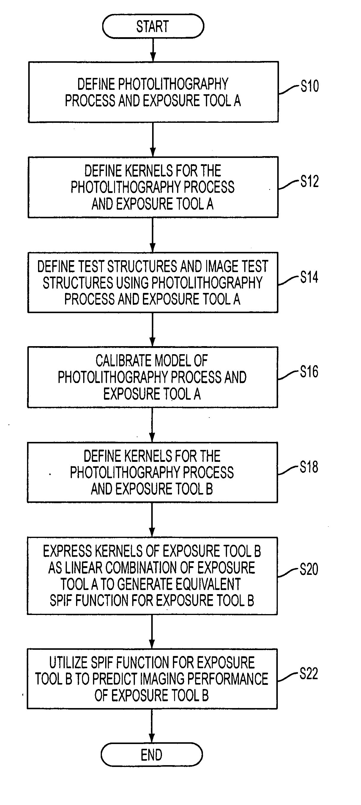
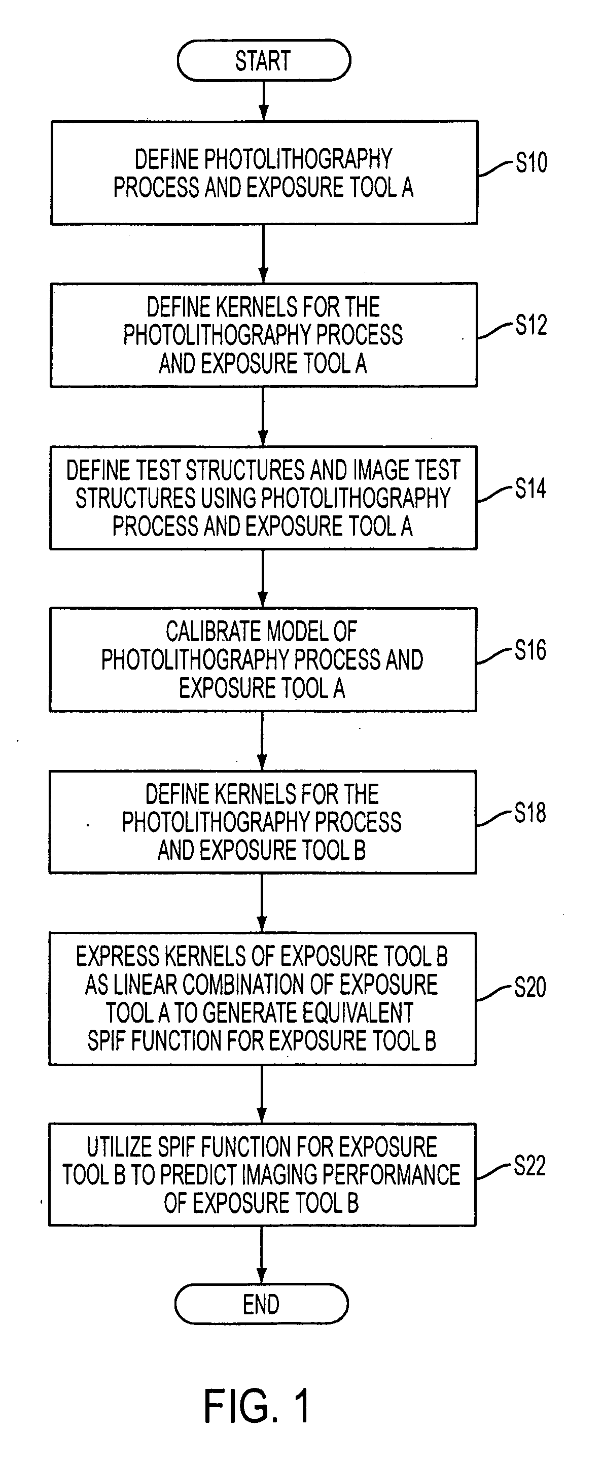
[0028] Disclosed herein is a method and apparatus for allowing a model, which is calibrated in conjunction with a first exposure tool and is capable of simulating the imaging performance of the first exposure tool, to be utilized to generate a second model capable of simulating the imaging performance of a second exposure tool without having to perform a calibration of the second model and second exposure tool. It is noted that the exemplary method detailed below utilizes an eigen function decomposition model (referred to as an Eigen Decomposition Model, or EDM), for modeling the performance of the imaging process. However, it is also possible to utilize the methods of the present invention with other types of models.

[0029] Prior to discussing the method of the present invention, a brief discussion regarding the generation of an eigen decomposition model is presented. A more detailed description of the generation of the eigen decomposition model can be found in U.S. patent applicat...


PUM

PropertyMeasurementUnit
wavelengthaaaaaaaaaa

Abstract

A method for generating models for simulating the imaging performance of a plurality of exposure tools. The method includes the steps of: generating a calibrated model for a first exposure tool capable of estimating an image to be produced by the first exposure tool for a given photolithography process, where the calibrated model includes a first set of basis functions; generating a model of a second exposure tool capable of estimating an image to be produced by the second exposure tool for the photolithography process, where the model includes a second set of basis functions; and representing the second set of basis functions as a linear combination of the first set of basis functions so as to generate an equivalent model function corresponding to the second exposure tool, where the equivalent model function produces a simulated image corresponding to the image generated by the second exposure tool for the photolithography process.

Description

[0001] This application claims the benefit of provisional application 60 / 539,997, filed on Jan. 30, 2004 and titled Method Of Predicting And Minimizing Model OPC Deviation Due To Mix / Match Of Exposure Tools Using A Calibrated Eigen Decomposition Model, which is herein incorporated by reference in its entirety.TECHNICAL FIELD OF THE INVENTION [0002] The field of the invention relates generally to a method, apparatus and program for utilizing models to simulate the aerial image resulting from a target mask pattern imaged by a given process, and more particularly relates to a method, apparatus and program product for allowing a model, which is calibrated utilizing a first exposure tool, to be utilized to predict the imaging results of a second exposure tool without having to recalibrate the model. BACKGROUND OF THE INVENTION [0003] Lithographic apparatus can be used, for example, in the manufacture of integrated circuits (ICs). In such a case, the mask may contain a circuit pattern cor...

Claims


Application Information

Patent Timeline
Patent Type & Authority Applications(United States)
IPC IPC(8): G03F1/00G03F1/36G03F7/20H01L21/027
CPCG03F1/144G03F1/36G03F7/70525G03F7/705G03F7/70516G03F7/70441G03F1/68G03F1/70G03F7/70433
Inventor SHI, XUELONGCHEN, JANG FUNG
Owner ASML NETHERLANDS BV
Why Eureka
Try Eureka