Catadioptric imaging system for high numerical aperture imaging with deep ultraviolet light

US20050179994A1Inactive Publication Date: 2005-08-18CORNING INC
12 Cites 44 Cited by

Patent Information

Authority / Receiving Office
US · United States
Current Assignee / Owner
Publication Date
2005-08-18
Estimated Expiration
Not applicable · inactive patent

Smart Images

  • Figure 1
    Figure 1
  • Figure 2
    Figure 2
  • Figure 3
    Figure 3
Patent Text Reader

Abstract

A catadioptric imaging system for micro-lithographic projection features a high numerical aperture objective where most of the focusing power is produced by reflection and refraction angles are limited to avoid additional aberration. A field correcting optic is appended to a Mangin mirror in an immersive configuration for raising the numerical aperture. The optical connection between the Mangin mirror and the field correcting optic is arranged to control refraction angles by limiting angles of incidence or refractive index differences. A radially symmetric polarizing effect is achieved in a pupil to improve image contrast.
Need to check novelty before this filing date? Find Prior Art

Description

BACKGROUND OF THE INVENTION

[0001] 1. Field of the Invention

[0002] The invention relates to imaging systems of the type in which a reflective surface provides substantial focusing power and more particularly relates to catadioptric reducing systems that exploit a combination of reflection and refraction for focusing purposes. The invention has particular applicability to Newtonian objectives for microlithographic imaging at high numerical apertures using deep ultraviolet light. The invention also contemplates issues of polarization management for imaging systems.

[0003] 2. Description of Related Art

[0004] Newtonian design forms in which focusing power is attained largely by reflection have been incorporated into microlithographic instruments to accurately project images while limiting chromatic aberrations. The chromatic advantages of Newtonian design forms over all-refractive imaging systems are particularly evident for imaging with ultraviolet light where transmissive material c...

Examples

Embodiment Construction

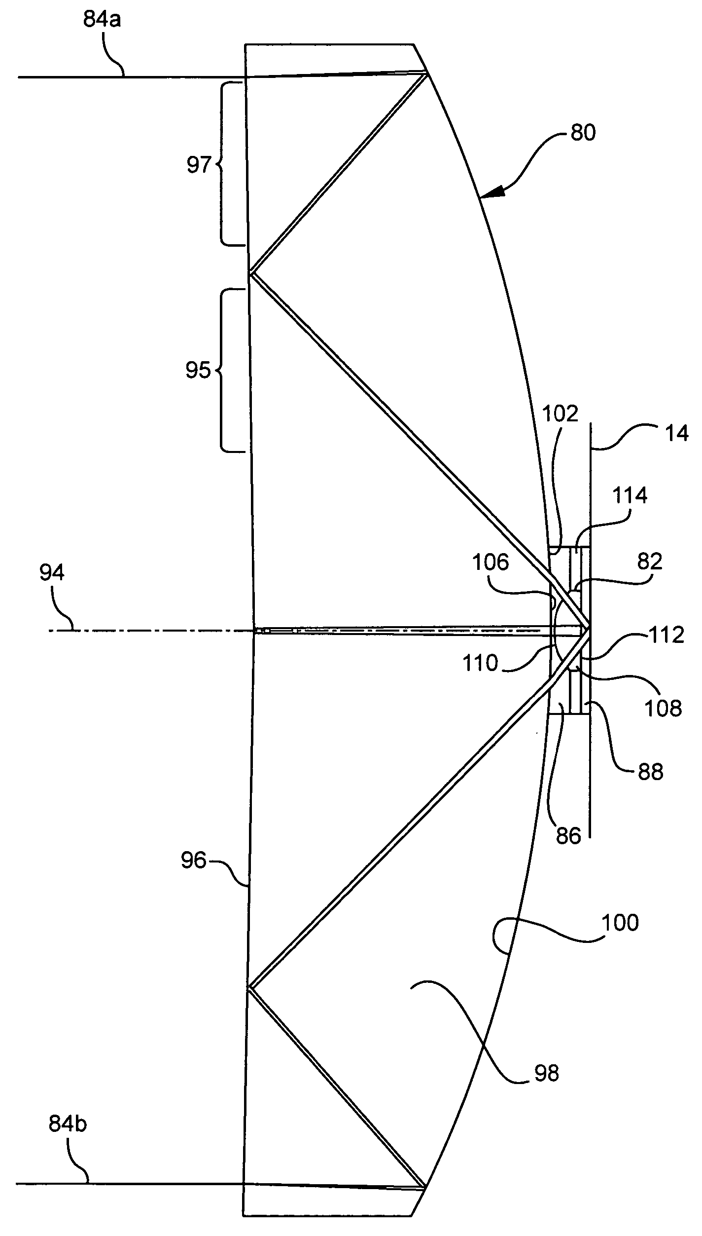
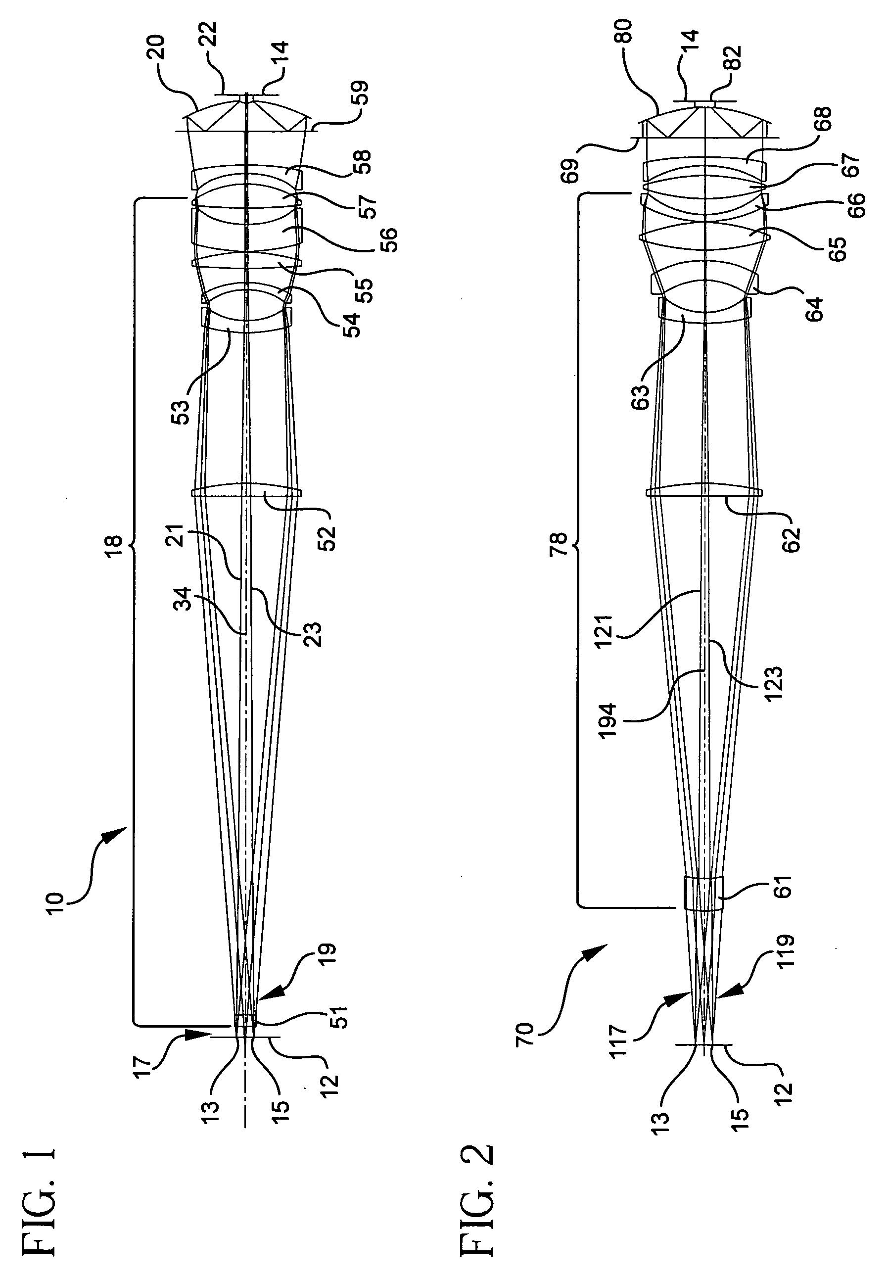
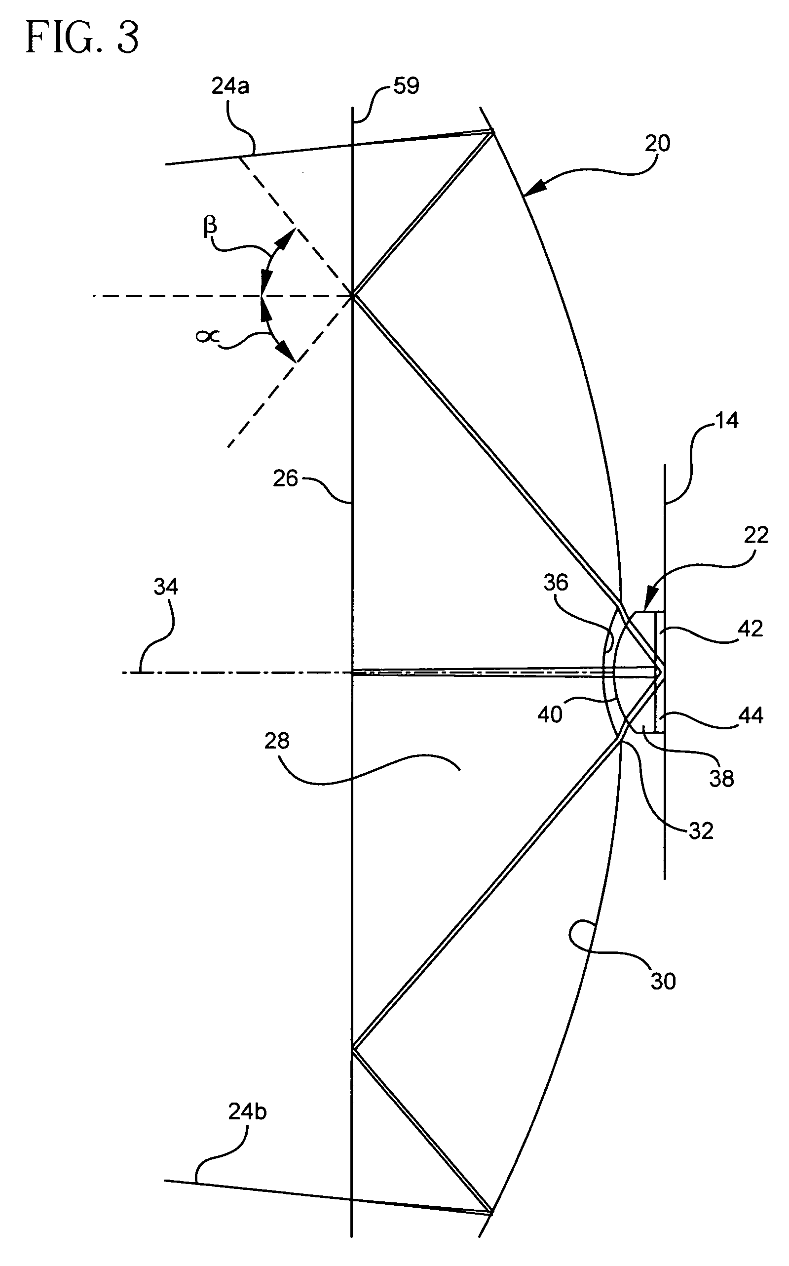
[0042] A catadioptric imaging system 10 for microlithographic projection is shown in FIG. 1 in an arrangement for imaging a reticle 12 (object) onto a resist 14 (image). An enlarged view of a double-reflecting Mangin mirror 20, which provides substantial focusing power for the imaging system 10, is shown in FIG. 3. An assembly 18 of largely refractive components is arranged for filling the aperture of the double-reflecting Mangin mirror 20 while assisting in the correction of aberrations. Throughout the assembly 18, refraction angles are minimized to avoid the introduction of unnecessary aberrations. A field correcting optic 22 operating in an immersion mode works in conjunction with the Mangin mirror 20 to produce a final image of the reticle 12 on a focal plane of the resist 14.

[0043] The focusing power of the double-reflecting Mangin mirror 20, which is positioned at or near a pupil of the imaging system 10, is apparent from the depicted paths of marginal rays 24a and 24b throug...