Fuel cell system and related method

a fuel cell and system technology, applied in the direction of driver interaction, non-vehicle mounted steering controls, climate sustainability, etc., can solve the problems of hard to take out the rated electric power and inability to generate electric power

Active Publication Date: 2005-08-18
NISSAN MOTOR CO LTD
View PDF7 Cites 65 Cited by
  • Summary
  • Abstract
  • Description
  • Claims
  • Application Information

AI Technical Summary

Benefits of technology

[0017] Furthermore, with the fuel cell system in which the secondary battery is installed as the electric storage unit, there are many probabilities for the secondary battery to be used under a state of charge (SOC) falling in a vicinity of 30% to 80% of a total battery capacity. That is, it is considered that the presence of such a secondary battery controlled so as to prevent the SOC from dropping below a value of 30% of a lower limit threshold ensures an energy for re-start-up or to assist a drive force and, further, the presence of control to preclude the SOC from exceeding 80% of an upper limit threshold allows the secondary battery to be used with the room open for recovering regenerative power.
[0022] Further, Japanese Patent Application Laid-Open Publication No. 2002-117876 discloses a structure wherein combustion heat resulting from combustion of fuel such as methanol is utilized to heat coolant. This is due to the fact that, to begin with, combustion heat of fuel has an increased heat value and an energy supplied from liquid fuel, such as methanol and gasoline, is greater than a capacity of the secondary battery, whereby there is less fear of a so-called energy shortage.
[0035] In the meantime, according to another aspect of the present invention, there is provided a method of controlling a fuel cell system provided with an electric power generating element including a fuel cell supplied with fuel gas and oxidizing gas to generate electric power and a warm-up mechanism achieving warm up of the electric power generating element, the method comprising: controlling the warm-up mechanism, in response to reception of a control signal transmitted from an external remote operator unit and commanding a start-up completion time at which start-up of the fuel cell system is to be completed through the warm-up of the electric power generating element, to allow the warm-up of the electric power generating element to be completed in alignment with the start-up completion time.

Problems solved by technology

Also, although the fuel cell has a capability of generating electric power at the temperature lower than such an operating temperature range, it is hard to take out the rated electric power because of a drop in an activity in reaction between fuel gas and oxidizing gas at the low temperature.
Moreover, with moisture contained in the polymer electrolyte membrane being frozen, no proton can transfer through the oxidizing gas electrode, resulting in an incapability of generating electric power.

Method used


Image

  • Fuel cell system and related method
  • Fuel cell system and related method
  • Fuel cell system and related method

Examples


first embodiment

[0052] First, referring to FIGS. 1 to 9, a fuel cell system and its related method of a first embodiment according to the present invention are described in detail.

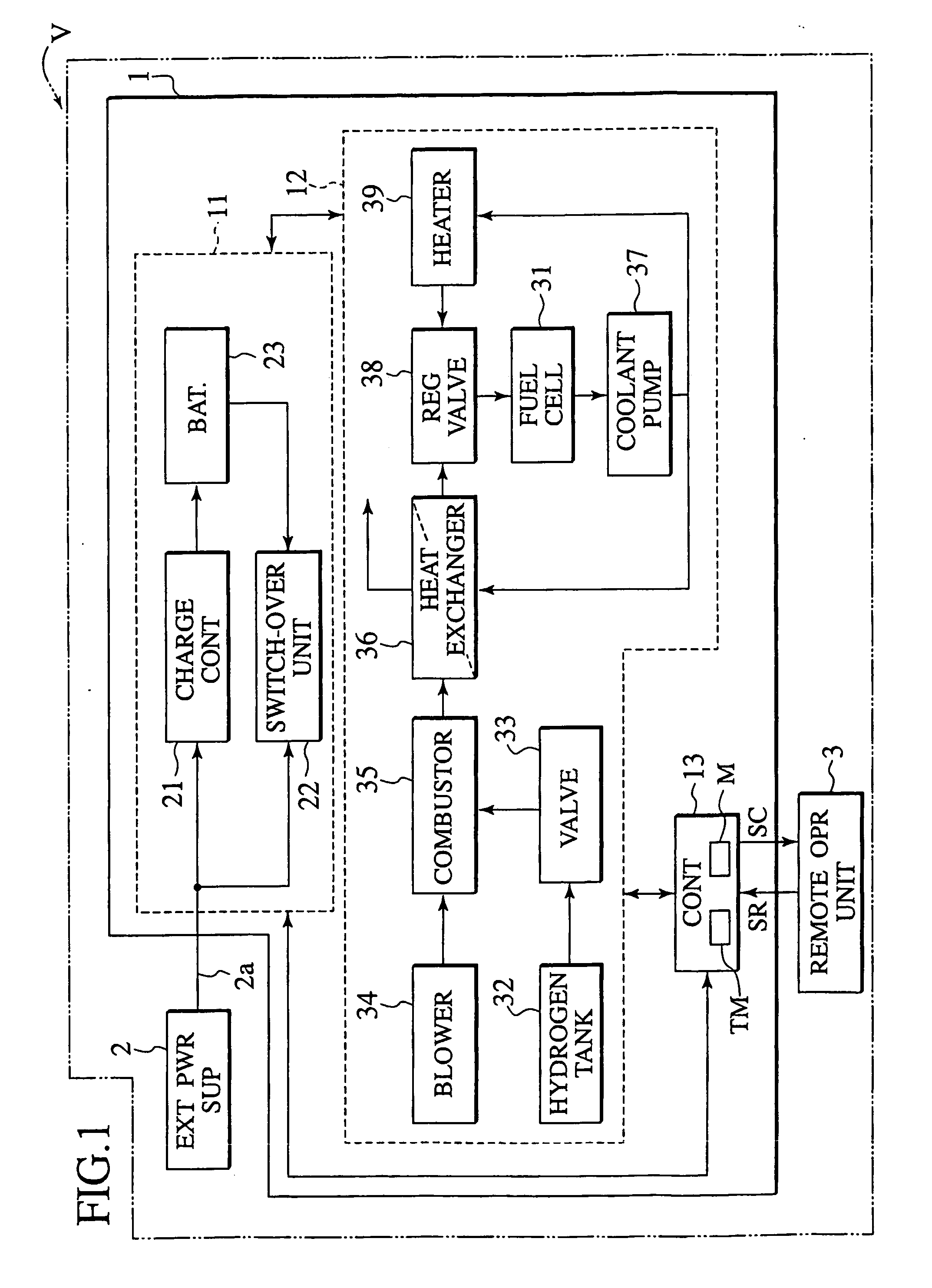
[0053]FIG. 1 is a block diagram illustrating a structure of the fuel cell system 1 of the presently filed embodiment and also illustrating the relationship between the fuel cell system, and an external power supply and a remote operator unit.

[0054] Structure of Fuel Cell System 1

[0055] As shown in FIG. 1, the fuel cell system 1 is installed on a moving object V such as an automobile and generates electric power as a power source of the moving object for supplying the electric power to its drive motor, which is not shown. The fuel cell system 1 is connected to the external power supply 2 through a cable 2a and, further, electrically connected through radio communication to the remote operator unit 3 that is to be held by a user.

[0056] Such a remote operator unit 3 includes, though not shown, an input section operated by...

second embodiment

[0117] Next, referring to FIGS. 10 to 14, a fuel cell system and its related method of a second embodiment according to the present invention are described in detail.

[0118]FIG. 10 is a block diagram illustrating a structure of a fuel cell system 100 of the presently filed embodiment while showing the relationship between the fuel cell system, and an external power supply and a remote operator unit. Also, a fuel cell operating section 120 of the presently filed embodiment differs from that of the first embodiment and, in view of such differential aspect, the same component parts and operations as those of the first embodiment bear the like reference numerals with description being predetermined in a suitably simplified form or omitted.

[0119] Structure of Fuel Cell System 100

[0120] The fuel cell system 100 of the presently filed embodiment includes the fuel cell operating section 120 which has a reformer 45 that reforms fuel such as gasoline to form hydrogen rich reformed gas, as fu...


PUM

PropertyMeasurementUnit
temperatureaaaaaaaaaa
operating temperatureaaaaaaaaaa
temperatureaaaaaaaaaa

Abstract

A fuel cell system (1, 100) adapted to be installed on a moving object (V) is provided with an electric power generating element (31, 45) including a fuel cell (31) supplied with fuel gas and oxidizing gas to generate electric power, a warm-up mechanism (21 to 23, 32 to 39, 41 to 50′) enabled to achieve warm up of the electric power generating element, and a controller (13), in response to reception of a control signal transmitted from an external remote operator unit (3) and commanding a start-up completion time at which start-up of the fuel cell system is to be completed through the warm-up of the electric power generating element, controlling the warm-up mechanism to allow the warm-up of at least the electric power generating element to be completed in alignment with the start-up completion time.

Description

TECHNICAL FIELD [0001] The present invention relates to a fuel cell system and its related method and, more particularly, to a fuel cell system, installed on a moving object, to commence start-up operation in response to a command remotely executed by a user, and its related method. BACKGROUND ART [0002] In recent years, a fuel cell favorable in view of environments focuses the spotlight of attention as a power source for a moving object such as an automobile, and development work has been undertaken to provide a fuel cell system adapted to achieve control for electric power generation of a fuel cell. [0003] Especially, as one of those fuel cell systems which attract public attention to be influential as a fuel cell of the moving object, it has been proposed to provide a polymer electrolyte fuel cell (PEFC) with a polymer electrolyte formed with a proton exchange membrane (PEM). [0004] Further, another fuel cell system has been proposed in which, in order to obtain hydrogen as fuel ...

Claims


Application Information

Patent Timeline
Patent Type & Authority Applications(United States)
IPC IPC(8): B60L11/18H01M8/04H01M8/00H01M8/06H01M8/10H01M16/00
CPCB60L11/1885B60L2250/22B60L11/1894B60L2260/56H01M8/04022H01M8/04268H01M8/0432H01M8/04626H01M8/04768H01M8/04776H01M8/0618H01M16/006H01M2250/20H01M2300/0082Y02T90/32Y02T90/34Y02E60/50B60L2240/36B60L2240/545B60L11/1892B60L58/31B60L58/33B60L58/34Y02T90/40Y02E60/10H01M8/04
Inventor NAKAJI, YOSHIHARU
Owner NISSAN MOTOR CO LTD
Why Eureka
Try Eureka