Device for cleaning vehicle exhaust gas

Inactive Publication Date: 2005-08-25
ET US HLDG
View PDF47 Cites 3 Cited by
  • Summary
  • Abstract
  • Description
  • Claims
  • Application Information

AI Technical Summary

Benefits of technology

[0006] This is achieved by providing a device with a filter body that has, at least in sections, an angular outer contour (as seen in a main direction of flow), and which has an unmachined outer surface at the angular outer contour. With the device according to the invention, the filter body is angular, at least in portions, and preferably has an overall angular outer contour. The overall angular outer contour is achieved by putting together a plurality of individual cuboid bodies. This results in a smaller number of individual bodies being machined on an outer surface. Preferably, there are no individual bodies that are machined on their outer surface, whereby an active filter surface area remains very large. The distribution of carbon-particulate matter and gas within the filter body is thus considerably more uniform than with machined filter bodies, and vice versa a smaller number of individual bodies is required in order to have the same cross-sectional area for the filter body. The uniform charging of the filter body with carbon-particulate matter results in a uniform combustion behavior with non-critical internal temperatures.

Problems solved by technology

Particularly, the filter body is turned so as to become rounded, which is very expensive owing to the extreme hardness of a ceramic material used to form the filter body.

Method used


Image

  • Device for cleaning vehicle exhaust gas
  • Device for cleaning vehicle exhaust gas
  • Device for cleaning vehicle exhaust gas

Examples


Embodiment Construction

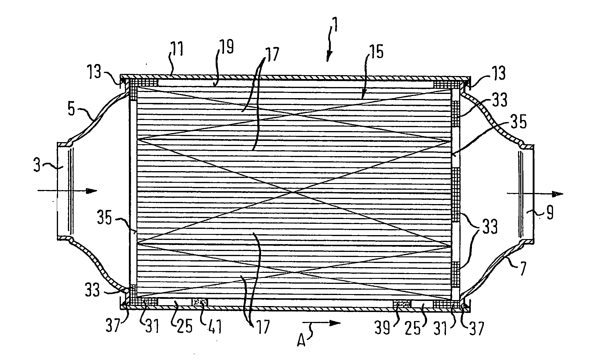
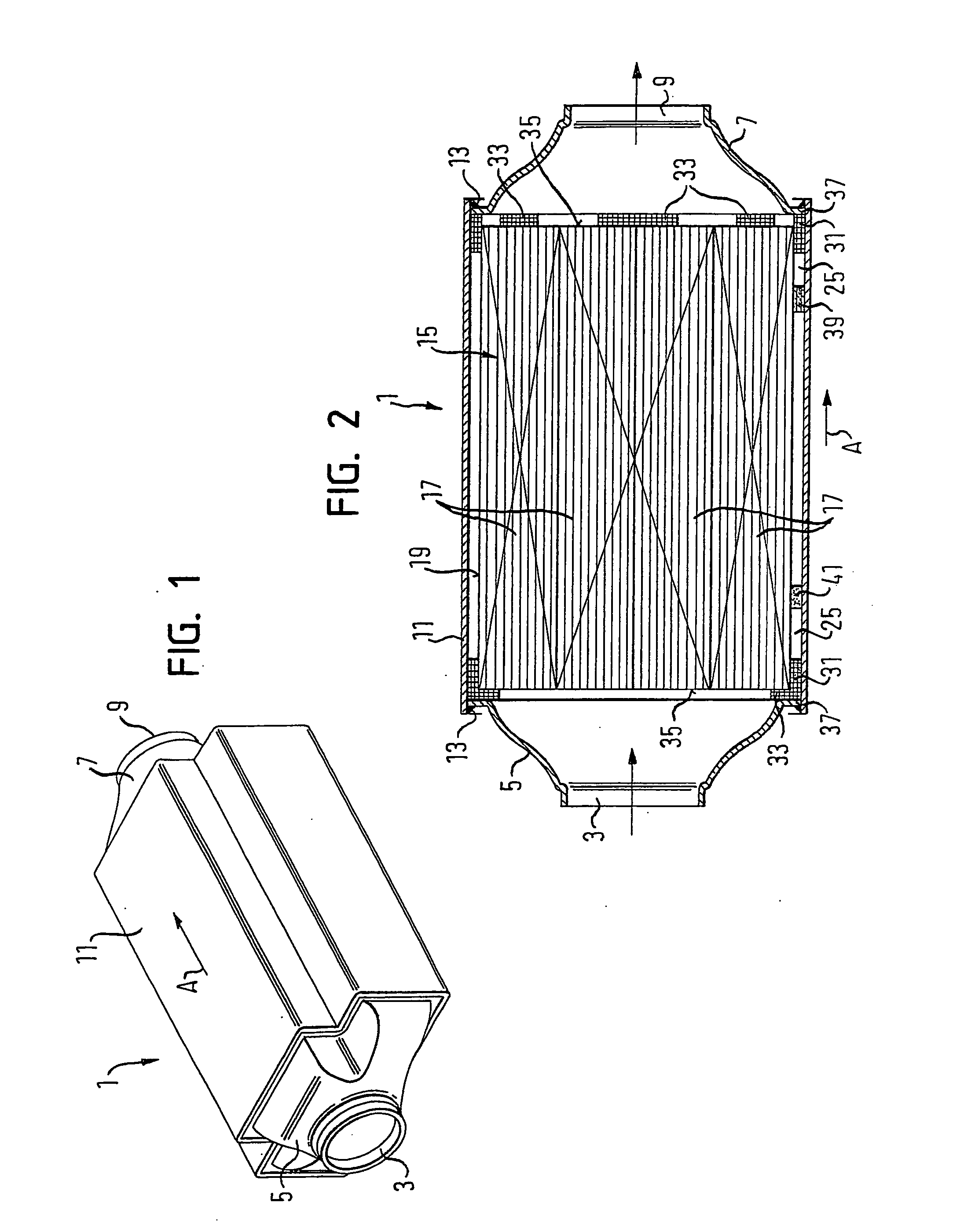
[0037]FIG. 1 shows a device for cleaning vehicle exhaust gas, provided in an exhaust tract of a vehicle. The device in the example shown, is a filter for diesel exhaust particles, also called a soot filter, but may also be appropriately configured as a catalytic converter.

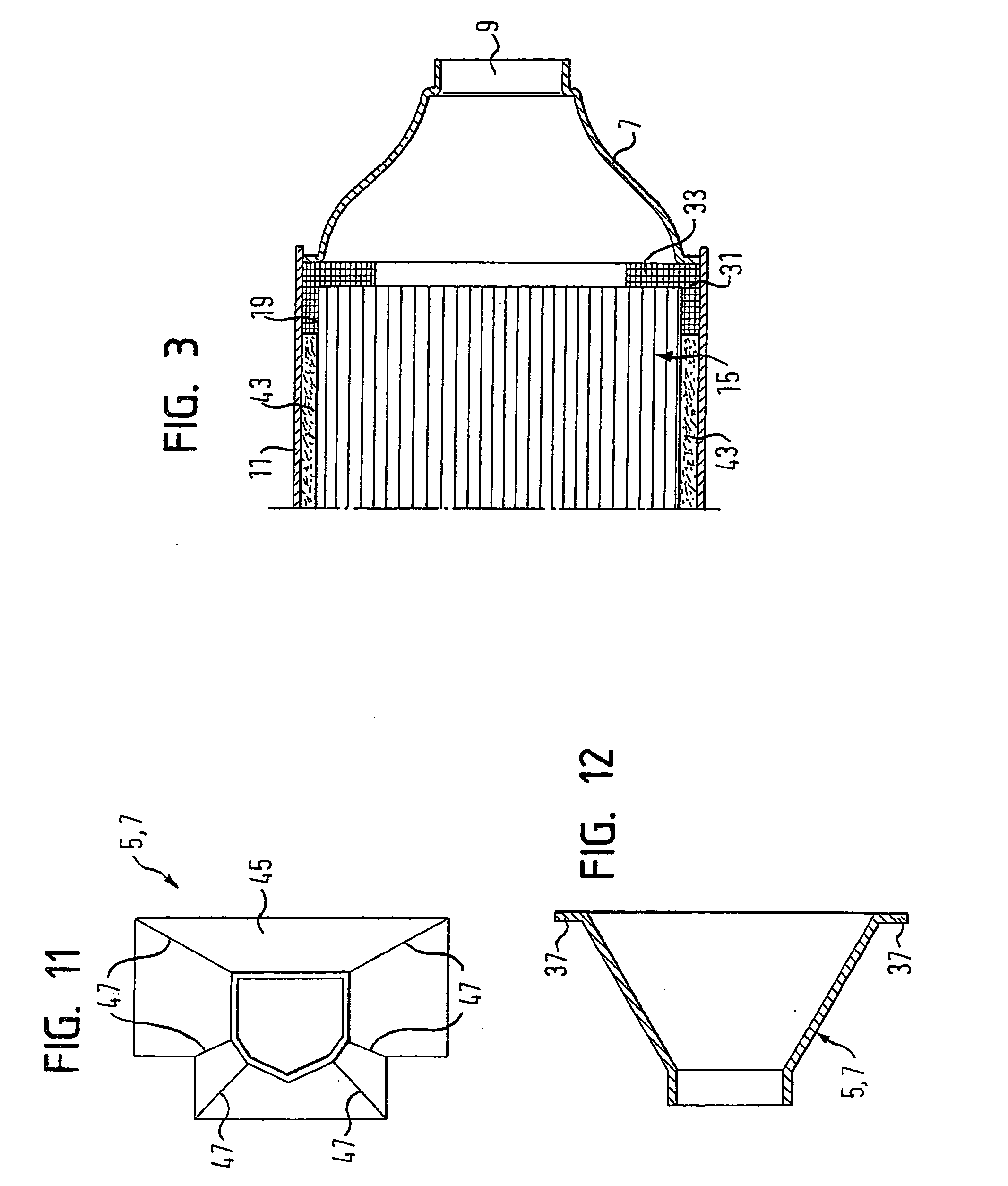
[0038] The device has an elongated housing 1 composed of several parts. The housing 1 includes one funnel-shaped portion 5 provided with an inflow port 3, and on an opposite end a funnel-shaped portion 7 having an effusion port 9. The housing 1 also includes a peripheral or circumferential wall 11 that is constituted by a deformed tube or formed by folding a sheet of metal. The funnel-shaped portions 5, 7 are welded with the circumferential wall 11, with the two funnel-shaped portions 5, 7 slightly protruding into an interior of the circumferential wall 11 (FIG. 2). Weld seams are referenced by reference symbol 13.

[0039] Accommodated in the interior of the housing 1 is a filter body 15 that is composed of a plura...


PUM

PropertyMeasurementUnit
thicknessaaaaaaaaaa
clamping forceaaaaaaaaaa

Abstract

A device for cleaning vehicle exhaust gas, especially a filter for diesel exhaust particulates or a catalytic converter, comprises a filter body including a plurality of individual cuboid bodies through which gas flows. The filter body has, at least in sections, an angular outer contour, as seen in a main direction of flow. The filter body also has an unmachined outer surface at the angular outer contour.

Description

RELATED APPLICATIONS [0001] This application claims priority to German Patent Application No. 10 2004 008 415, which was filed on Feb. 20, 2004. BACKGROUND OF THE INVENTION [0002] The invention relates to a device for cleaning vehicle exhaust gas, especially to a filter for diesel exhaust particulates. The device includes a filter body through which gas flows and which is composed of a plurality of individual cuboid bodies. A housing surrounds the filter body. [0003] Such filter bodies, also called monolith bodies or substrates, are usually composed of extruded, one-piece (monolith) individual bodies made from a material, such as silicon-carbide (SiC), and which are glued to each other. These elongated individual bodies in their commercially available form have a square cross-section. On one end face, the filter bodies have numerous inflow channels that end in blind holes, and which are arranged in a honeycomb-like pattern. Traditionally, the inflow channels have a square cross-sect...

Claims


Application Information

Patent Timeline
Patent Type & Authority Applications(United States)
IPC IPC(8): F01N3/021F01N3/022F01N3/28
CPCF01N3/0211F01N3/0222F01N3/2853F01N2260/06F01N2260/10Y02T10/20F01N2330/06F01N2330/30F01N2350/04F01N2350/06F01N2450/20F01N2310/14Y02A50/20Y02T10/12
Inventor NOLLER, CHRISTOPHKRONER, PETERSTEINHAUSER, OTTO
Owner ET US HLDG
Why Eureka
Try Eureka