
Method for using a microwave source for reactive atom-plasma processing

a technology of atomplasma and microwave source, which is applied in the field of surface modification using gas plasma, can solve the problems of icp torch footprint being too large for fine-scale modifications, certain limitations and attributes, and not being desirable for specific applications, and achieve the effect of increasing the velocity of gasses flowing

Inactive Publication Date: 2005-08-25
RAPT INDS
View PDF5 Cites 10 Cited by
  • Summary
  • Abstract
  • Description
  • Claims
  • Application Information

AI Technical Summary

Benefits of technology

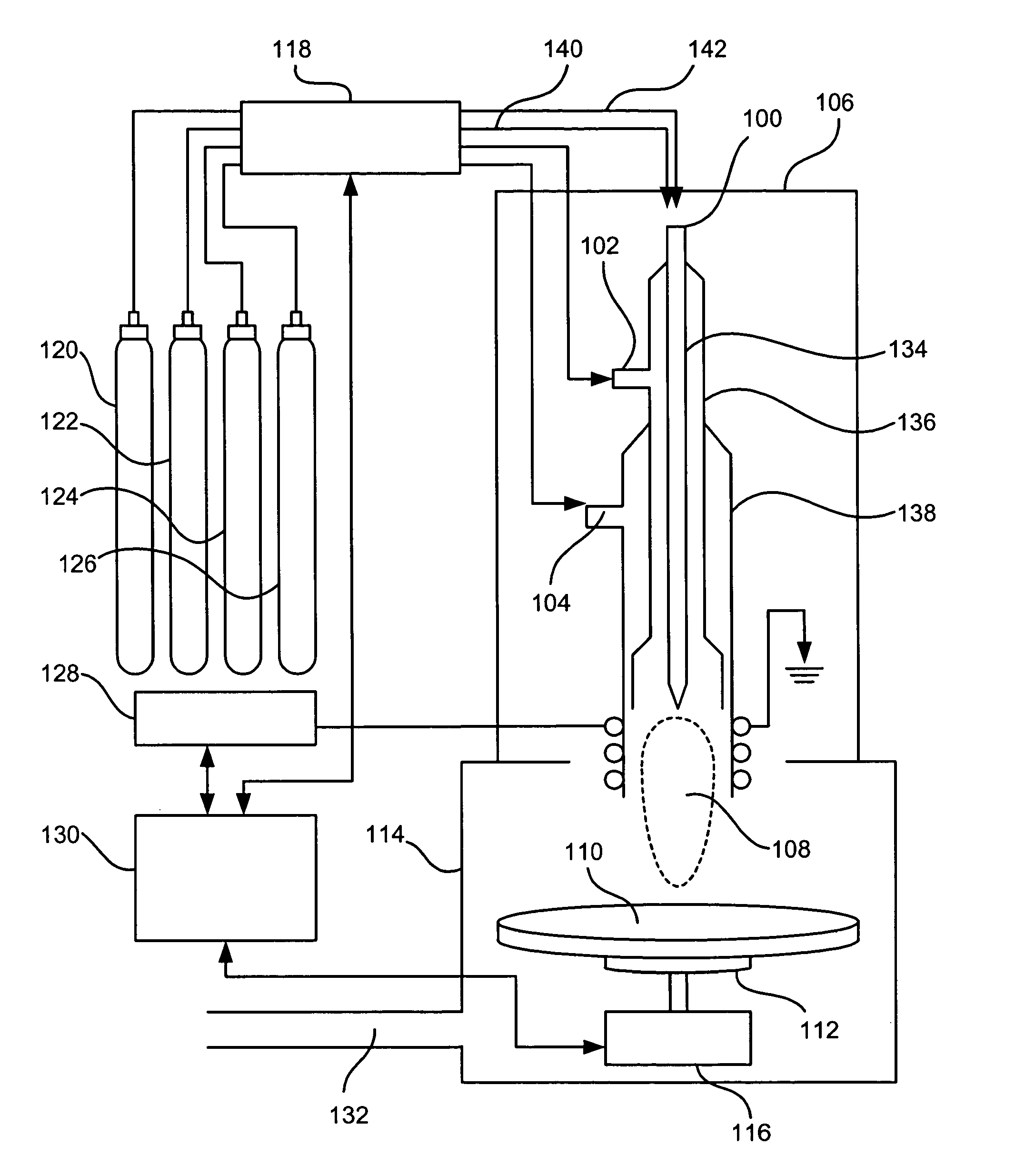
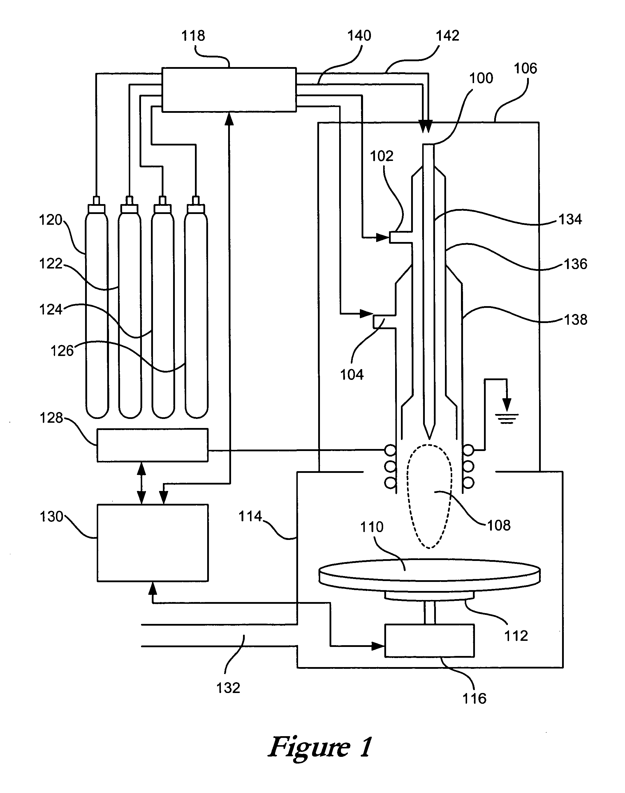
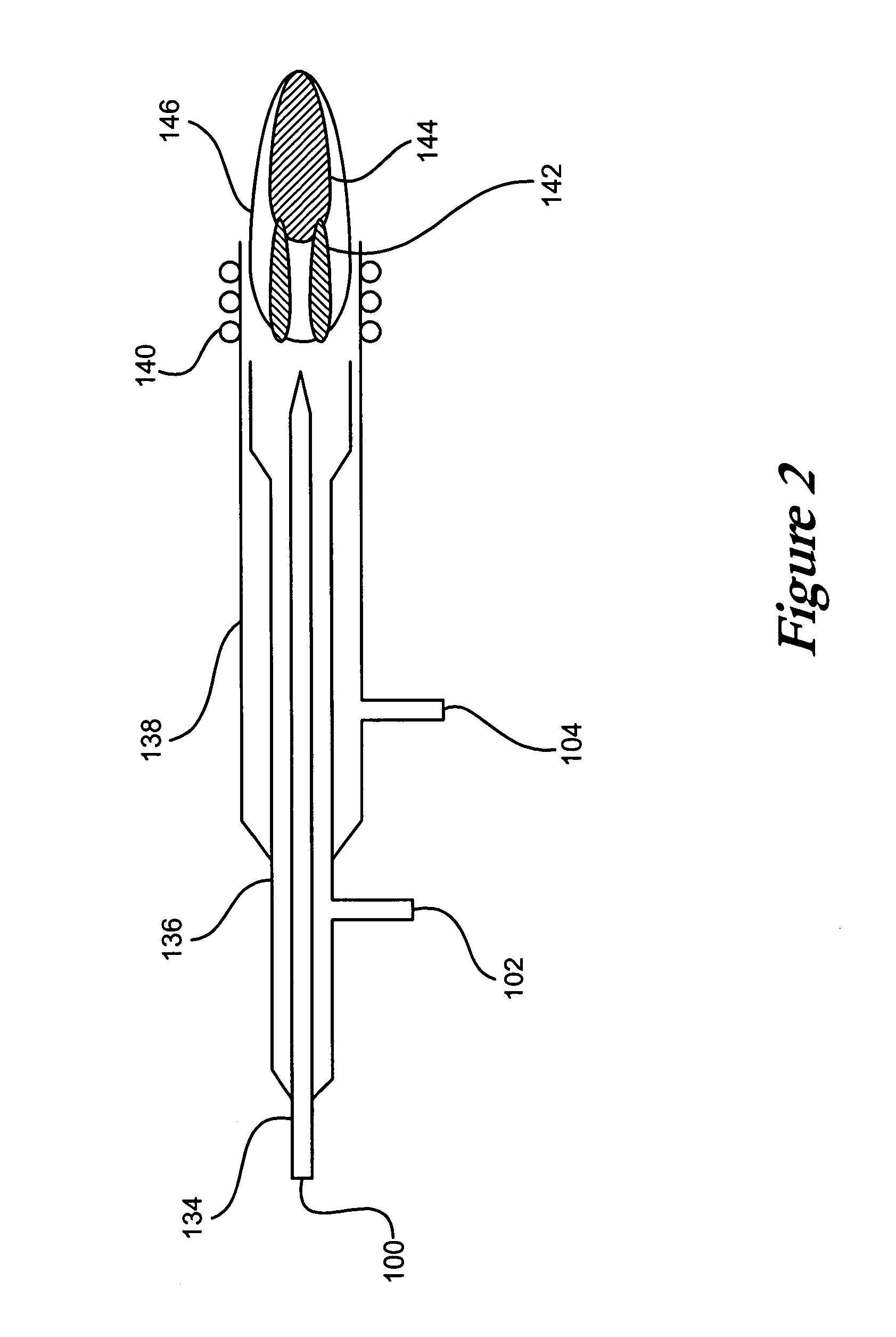
[0014] A gas source can direct a flow of process gas into the microwave induced plasma torch, which can include two concentric tubes to receive the process gasses. A flow regulator can maintain the flow of process gas between about 0.5 I / min and about 14 I / min. A microwave cavity can surround at least a portion of the microwave-induced plasma torch, which can receive microwaves from a microwave source in order to excite atoms in the plasma. A helical insert can be placed between the two concentric tubes in order to hold the spacing of the tubes, as well as to increase the velocity of the gasses flowing through the tubes and cool the tubes themselves. An external power source, such as a 2.45 GHz power source, can be used to supply energy to the microwave cavity. The cavity itself can be tunable, such as through use of a moveable plunger. A gas sheath can be attached to the cavity to shield the microwave-induced plasma from the atmosphere.

Problems solved by technology

The use of a conventional ICP torch can come with certain limitations and attributes, however, that may be less than desirable for specific applications.
For instance, the footprint of an ICP torch maybe too large for fine-scale modifications.
The flow of host gas for an ICP torch is a source of expense, and it would be more cost effective to use a lower flow rate in order to reduce the cost-per-part processed by the system.
A device using an ICP torch can be somewhat bulky, limiting the mobility and ease-of-use of the device.
An ICP torch can also place a relatively high heat load on the part being processed, which may be unacceptable for certain workpieces and materials.
An ICP torch requires a certain amount of shielding, which adds to the cost of the device.
A plasma box, which itself can be bulky and add additional expense, is often used to shield an operator from radio frequency energy generated during a process, and / or from UV light produced by a plasma.
The parts that make up the ICP torch itself are also relatively expensive, and are not highly-available.
Early MIP work suggested that such a plasma was unable to easily vaporize liquid samples.

Method used


Image

  • Method for using a microwave source for reactive atom-plasma processing
  • Method for using a microwave source for reactive atom-plasma processing
  • Method for using a microwave source for reactive atom-plasma processing

Examples


Embodiment Construction

[0021] A microwave-induced atmospheric pressure plasma can be an appropriate atomnization tool for several applications of a reactive atom plasma process. A microwave-induced plasma (MIP) source has proven to have a number of attributes that complement, or even surpass in some applications, the use of an ICP tool or a flame as an atomization source. Some of these advantages include a smaller footprint, which can be as low as about 0.5 mm or less, or from about 1 mm or less to about 10 mm or more, as well as a smaller and simpler device that can operate on lower flow rates of host gas and can even be run on air, nitrogen or oxygen. Flow rates for one MIP device can range between about 0.5 I / min to about 13 I / min or so, although flow rates of less than 0.5 I / min and above 13 I / min are also possible. Host gases can include, for example, Argon, Helium, nitrogen, air, CF4, oxygen and / or hydrogen. In fact, any gas phase material or combination thereof could be used.

[0022] The plasma can ...


PUM

PropertyMeasurementUnit
poweraaaaaaaaaa
poweraaaaaaaaaa
poweraaaaaaaaaa

Abstract

Reactive atom plasma processing (RAP) can be used to shape, polish, planarize, and clean surfaces of difficult materials with minimal subsurface damage. An improved RAP device utilizes a microwave-induced plasma (MIP) source instead of a conventional ICP torch to modify these surfaces. The use of MIP provides for a smaller footprint, finer detail, simpler and enhanced movement capabilities, lower heat load, fewer shielding requirements, and cheaper construction and operation than ICP. This description is not intended to be a complete description of, or limit the scope of, the invention. Other features, aspects, and objects of the invention can be obtained from a review of the specification, the figures, and the claims.

Description

CLAIM OF PRIORITY [0001] This application claims priority from U.S. patent application Ser. No. 10 / 383,478, entitled “Apparatus and Method for Using a Microwave Source for Reactive Atom Plasma Processing” by Jeffrey W. Carr, filed Mar. 7, 2003 (Attorney Docket No. CARR-01001US0), incorporated herein by reference.FIELD OF INVENTION [0002] The field of the invention relates to the modification of surfaces using a gas plasma. BACKGROUND [0003] U.S. patent application Ser. No. 10 / 008,236 discloses the use of reactive atom plasma processing to modify surfaces of difficult materials with minimal subsurface damage. The apparatus and methods of various embodiments use a conventional inductively-coupled plasma (ICP) torch. The workpiece and plasma torch are moved with respect to each other, such as by translating and / or rotating the workpiece, the plasma, or both. The plasma discharge from the ICP torch can be used to shape, planarize, polish, clean and / or deposit material on the surface of ...

Claims


Application Information

Patent Timeline
Patent Type & Authority Applications(United States)
IPC IPC(8): C23C16/511C23C16/513H01L21/00H05H1/30
CPCC23C16/511C23C16/513H05H1/30H01J37/32357H01L21/67069H01J37/32192
Inventor CARR, JEFFREY W.
Owner RAPT INDS
Learn More