Low profile antenna

Inactive Publication Date: 2005-08-25
ROUND ROCK RES LLC
View PDF10 Cites 5 Cited by
  • Summary
  • Abstract
  • Description
  • Claims
  • Application Information

AI Technical Summary

Benefits of technology

[0006] The shortcomings described above are overcome by the present invention which discloses a low profile antenna having relatively high radiation resistance, wide bandwidth and utilizes a single conductor and RF source. In accordance with an exemplary embodiment of the invention, the upper horizontal portion and the lower horizontal portion of the double inverted-L antenna are respectively

Problems solved by technology

One item of a radio communications device which cannot easily be reduced in size, however, is the antenna.
Typically the a

Method used


Image

  • Low profile antenna
  • Low profile antenna
  • Low profile antenna

Examples


Embodiment Construction

[0023] In the following detailed description, reference is made to the accompanying drawings which form a part hereof, and in which is shown by way of illustration specific embodiments in which the invention may be practiced. These embodiments are described in sufficient detail to enable those of ordinary skill in the art to make and use the invention, and it is to be understood that structural and logical changes may be made to the specific embodiments disclosed without departing from the spirit and scope of the present invention.

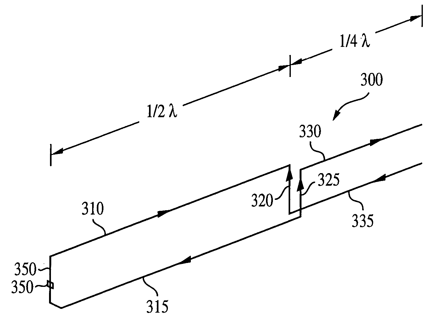
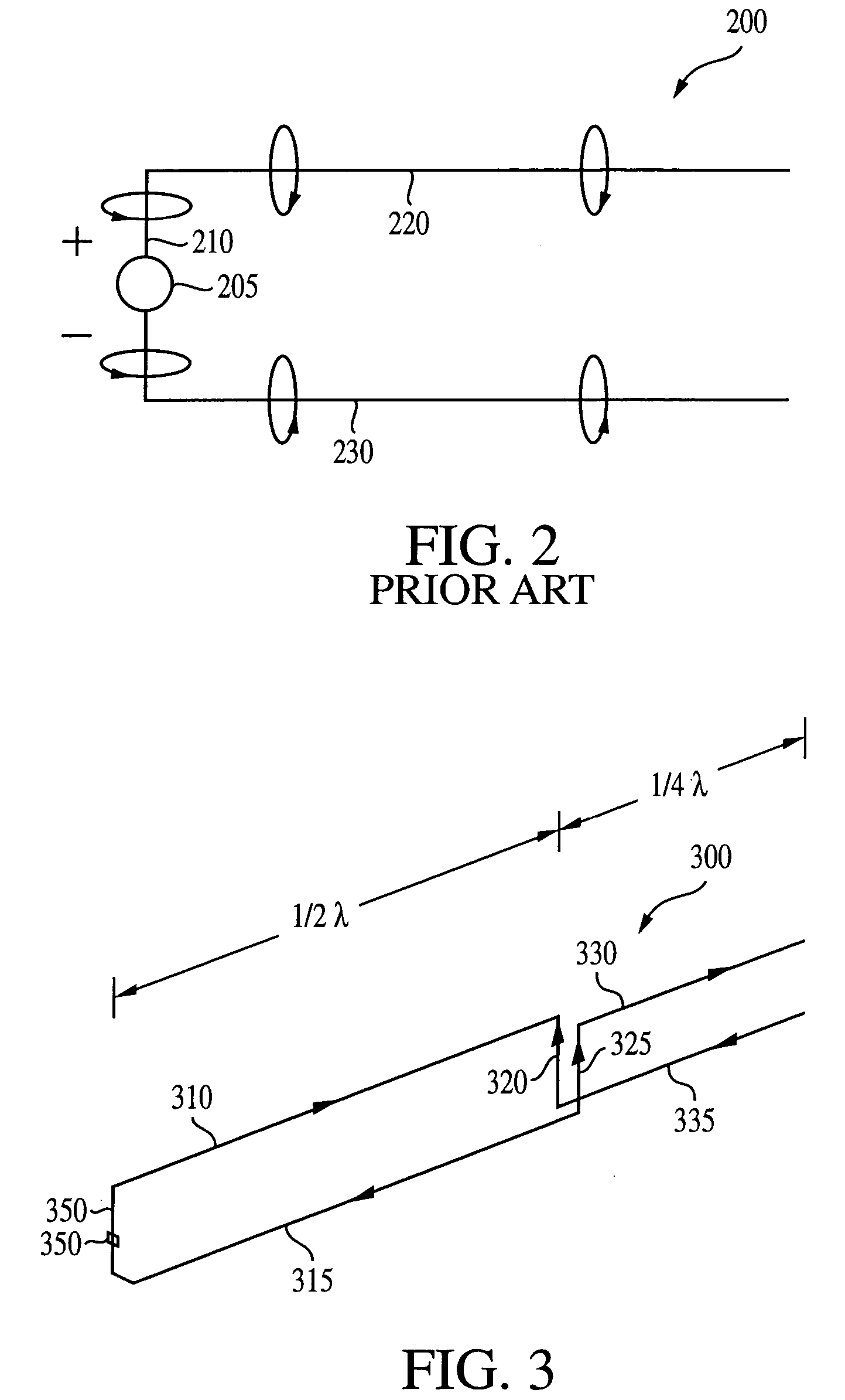
[0024]FIG. 3 depicts a low profile antenna configuration 300, in accordance with an exemplary embodiment of the invention.

[0025] The left-hand portion of the antenna 300 is essentially the same as that of the FIG. 2 antenna 200. The antenna 300 has a power source (e.g., an RF source) 305 at the left-most vertical portion 350, and two horizontal portions 310, 315. The antenna 300 also has two vertical portions 320, 325 a distance of 180-degrees (½λ) from ...


PUM


Abstract

A low profile antenna having relatively high radiation resistance, wide bandwidth and which utilizes a single conductor and RF source is disclosed. In accordance with an exemplary embodiment, the upper horizontal portion and the lower horizontal portion of the double inverted-L antenna are respectively brought down and up (without being physically connected) at a distance of approximately 180 degrees (½λ) from the RF source so as to form two additional vertical portions of the antenna. This is followed by two approximately 90-degree (¼λ) horizontal conductors portion. The resulting radiation resistance of the low profile antenna is approximately three-times that of a double inverted-L antenna.

Description

FIELD OF THE INVENTION [0001] The present invention relates to the field of radio communications, and more specifically, to a low profile antenna used in the field of radio communications. BACKGROUND OF THE INVENTION [0002] As circuit size decreases in many mobile communications devices, and associated plastics housings and the like reduce in size, mobile radio handsets are also decreasing in size. One item of a radio communications device which cannot easily be reduced in size, however, is the antenna. Typically the antenna is one half or one quarter of a wavelength in length along at least one axis and as such cannot easily be reduced. [0003] An antenna radiates electromagnetic waves when there is an acceleration of charge through the conductor. This produces a magnetic field, which then produces electromagnetic (EM) radiation. One type of antenna known to those skilled in the art is the resonant dipole antenna 100, depicted at FIG. 1. A radio frequency (RF) source 120 is depicted...

Claims


Application Information

Patent Timeline
IPC IPC(8): H01Q9/30H01Q9/38H01Q11/12H01Q21/00
CPCH01Q9/38H01Q9/30
Inventor CUTHBERT, DAVID R.
Owner ROUND ROCK RES LLC
Why Eureka
Try Eureka