Fast model-based optical proximity correction

Inactive Publication Date: 2005-08-25
GLOBALFOUNDRIES INC
View PDF2 Cites 88 Cited by
  • Summary
  • Abstract
  • Description
  • Claims
  • Application Information

AI Technical Summary

Benefits of technology

[0033] 3. Improved accuracy of the image due to the inclusion of non-scalar effects, including, but not limited to effects of the vector

Problems solved by technology

However, in extending model-based-optical-proximity-correction (MBOPC) to the sub-100 nm dimensions of next-generation IC products, the prior art has a number of limitations.
However, the computational efficiency of this procedure is not adequate for MBOPC.
However, the approaches of Adam et al. and Hafeman et al. ignore the z-component of the field, and do not take into account effects such as lens birefringence, tailored source polarization, or blur from the resist or mask.
As NA and lens complexity increases, the polarization state of the output beam is changed by cumulative polarization-dependent reflection losses that arise at the surfaces of the lens elements.
Attainable performance in the antireflection coatings that inhibit these losses will become increasingly poor as wavelength decreases into the deep ultraviolet (UV).
The anti-reflective (AR) films that

Method used


Image

  • Fast model-based optical proximity correction
  • Fast model-based optical proximity correction
  • Fast model-based optical proximity correction

Examples


Embodiment Construction

[0040] In the following description, numerous specific details may be set forth to provide a thorough understanding of the present invention. However, it will be obvious to those skilled in the art that the present invention may be practiced without such specific details. In other instances, well-known features may have been shown in block diagram form in order not to obscure the present invention in unnecessary detail.

[0041] Refer now to the drawings wherein depicted elements are not necessarily shown to scale and wherein like or similar elements are designated by the same reference numeral through the several views.

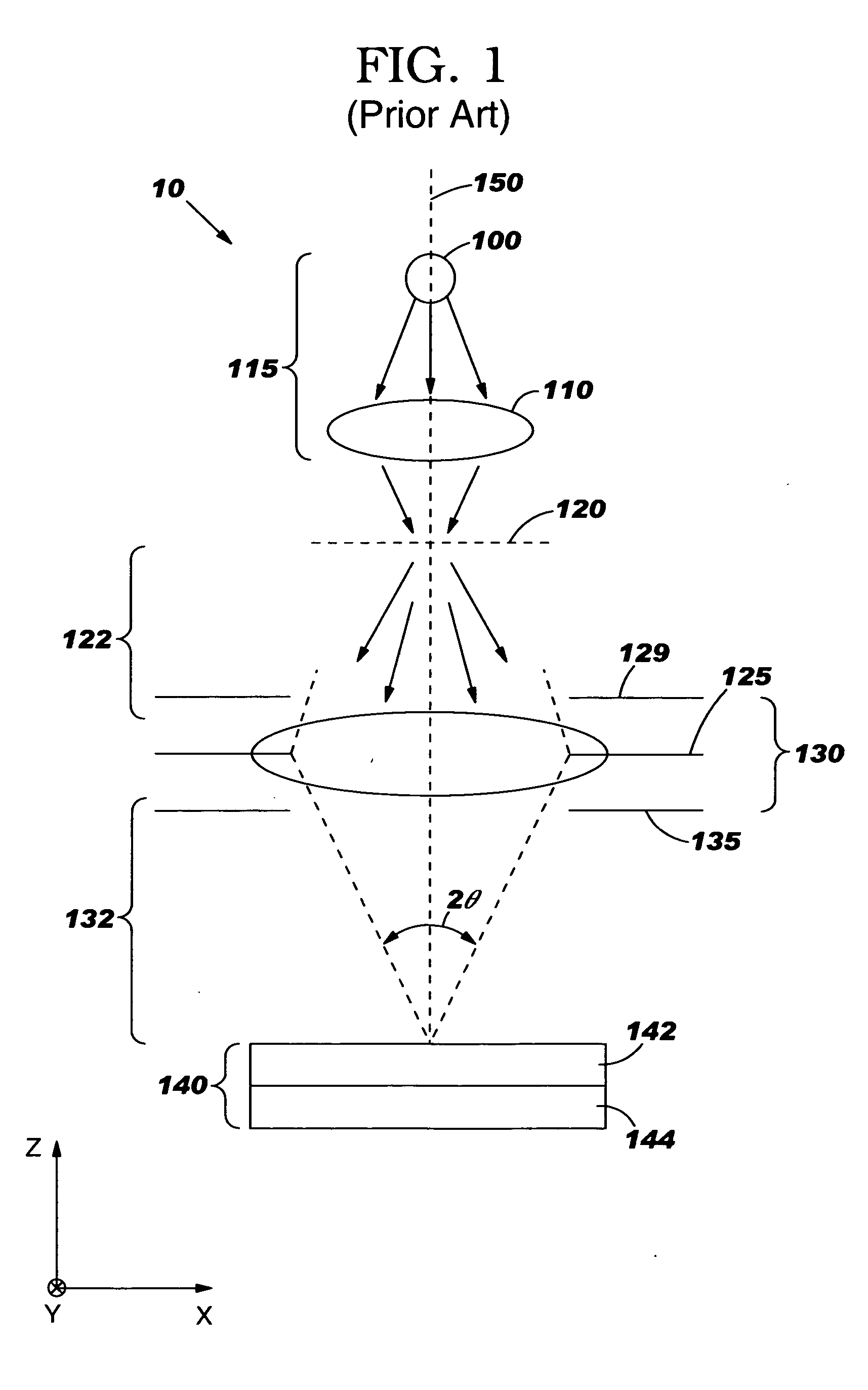
[0042]FIG. 1 illustrates a schematic diagram of Kohler projection system 10 used in optical lithography. An energy source 100 provides actinic energy (actinic energy is that illumination energy that will drive the reaction in the resist), which may be projected through a condenser lens 110 to a patterned mask or reticle (120). Together, the source 100 and the condense...


PUM


Abstract

An efficient method and system is provided for computing lithographic images that takes into account vector effects such as lens birefringence, resist stack effects and tailored source polarizations, and may also include blur effects of the mask and the resist. These effects are included by forming a generalized bilinear kernel, which is independent of the mask transmission function, which can then be treated using a decomposition to allow rapid computation of an image that includes such non-scalar effects. Dominant eigenfunctions of the generalized bilinear kernel can be used to pre-compute convolutions with possible polygon sectors. A mask transmission function can then be decomposed into polygon sectors, and weighted pre-images may be formed from a coherent sum of the pre-computed convolutions for the appropriate mask polygon sectors. The image at a point may be formed from the incoherent sum of the weighted pre-images over all of the dominant eigenfunctions of the generalized bilinear kernel. The resulting image can then be used to perform model-based optical proximity correction (MBOPC).

Description

TECHNICAL FIELD [0001] The present invention relates in general to manufacturing processes that require lithography and, in particular, to methods of designing photomasks and optimizing lithographic and etch processes used in microelectronics manufacturing. BACKGROUND INFORMATION [0002] Today's integrated circuits (ICs) contain features which are not easily resolved by available lithography tools, so proper printing of critical feature dimensions (CDs) requires that compensating adjustments be made to the IC shapes deployed on the mask. In so-called model-based optical-proximity-correction (MBOPC), the appropriate adjustments are determined by simulating the lithographic process, and in particular, providing a means to simulate the image at the wafer plane. Ultimately, a determination of the image formed in the resist layer (e.g. the latent resist image) is desired, but often the aerial image at the wafer plane is used as an approximation for the latent image in the resist. [0003] C...

Claims


Application Information

Patent Timeline
IPC IPC(8): G03F1/08G03B27/54G03F7/20
CPCG03F1/36G03F7/705G03F7/70441
Inventor ROSENBLUTH, ALAN E.GALLATIN, GREGG M.GORDON, RONALD L.SEONG, NAKGEUONLVOV, ALEXEY Y.HINSBERG, WILLIAM D.HOFFNAGLE, JOHN A.HOULE, FRANCES A.SANCHEZ, MARTHA I.
Owner GLOBALFOUNDRIES INC
Why Eureka
Try Eureka