Circuit arrangement provided with a phase-locked loop and transmitter-receiver with said circuit arrangement

a technology of phase lock loop and circuit arrangement, which is applied in the direction of angle modulation details, angle demodulation by phase difference detection, electrical apparatus, etc., can solve the problem that specifics cannot be observed any longer, and achieve the effect of little complexity

Active Publication Date: 2005-08-25
TAHOE RES LTD
View PDF8 Cites 23 Cited by
  • Summary
  • Abstract
  • Description
  • Claims
  • Application Information

AI Technical Summary

Benefits of technology

[0013] In line with the present principle, the output signal from the oscillator in the phase locked loop or a signal derived therefrom is mixed with the reference source's provided reference signal for the phase locked loop or with a signal derived therefrom. The output signal from this mixing operation, that is to say the output signal from the frequency mixer in the trimming path, is then demodulated and is supplied to a control input on the modulator for trimming purposes. It is thus possible to perform amplitude trimming with little complexity.
[0014] In the case of the present modulator, the principle described allows not only production-related tolerances but also temperature-related drift effects and aging effects to be compensated for.
[0015] The present principle is shown to particular advantage when the phase locked loop is developed to form a two-point modulator.

Problems solved by technology

However, this principle has the drawback that drift effects can cause the carrier frequency to change in open operation, which means that specifications cannot be observed any longer.
However, this would have the associated drawback that it would be necessary to provide an additional phase locked loop which, in the case of a heterodyne receiver, would need to be set to a frequency which corresponds to the differential frequency between the transmission frequency and the intermediate frequency.

Method used


Image

  • Circuit arrangement provided with a phase-locked loop and transmitter-receiver with said circuit arrangement
  • Circuit arrangement provided with a phase-locked loop and transmitter-receiver with said circuit arrangement
  • Circuit arrangement provided with a phase-locked loop and transmitter-receiver with said circuit arrangement

Examples


Embodiment Construction

[0035] In the text below, identical reference symbols denote parts which are the same or have the same action.

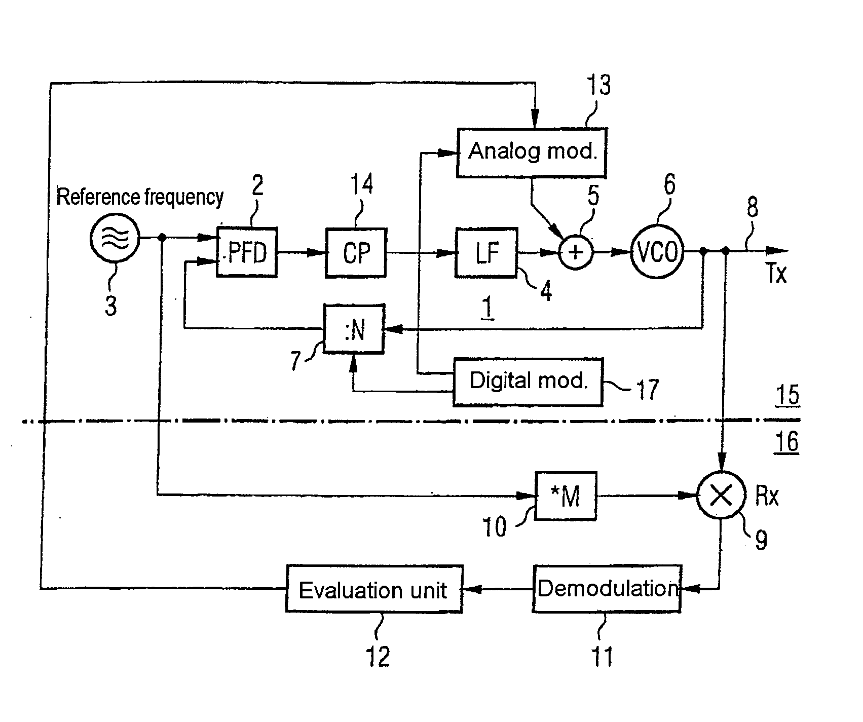
[0036] In the case of such two-point modulation with a combination of digital and analog modulation, it should be remembered that the analog and digital modulation signals are in phase and that there is a good match between the amplitudes of these two signals. Manufacturing tolerances (which are unavoidable in the case of mass production) in the device components, which are of significance to analog modulation and, by way of example, influence the modulation gradient, the modulation voltage generation etc., mean that it is necessary to perform amplitude trimming between the analog and the digital modulation following production of a radio transmitter of this type. If the intention is also to take into account temperature influences on the parameters of the devices used, it is desirable for such trimming to be carried out not just once during production but also prior to eve...


PUM


Abstract

The invention specifies a circuit arrangement with a phase locked loop (1), which can be used as a mobile radio transmitter, in particular. The reference frequency for the PLL (1), which is provided by means of the source (3), is multiplied by a multiplier (10) and is down-converted to an intermediate-frequency level in a down-conversion mixer (9) using the output signal from the PLL, and is evaluated such that a modulator (13) connected to the input of the oscillator (6) can be trimmed. The inventive principle is used to advantage in two-point modulators and allows inexpensive, integratable mobile radio transmitters with good noise characteristics.

Description

REFERENCE TO RELATED APPLICATIONS [0001] This application is a continuation of PCT / DE03 / 002118, which was not published in English, that claims the benefit of the priority dates of German Patent Application Nos. 10228759.7, filed on Jun. 27, 2002, and 10243382.8, filed Sep. 18, 2002 the contents of which are herein incorporated by reference in their entirety.FIELD OF THE INVENTION [0002] The present invention relates to a circuit arrangement with a phase locked loop and to a transceiver with the circuit arrangement. BACKGROUND OF THE INVENTION [0003] A plurality of architectures for mobile radio transmitters are known which can be produced with little complexity. Particularly in the case of radio transmitters which operate using time slots, “bursts”, it is appropriate to use “open loop modulation”. In this case, a phase locked loop first locks onto the desired transmission frequency. Prior to the actual transmission of useful data, the control loop is opened and the carrier is modul...

Claims


Application Information

Patent Timeline
Patent Type & Authority Applications(United States)
IPC IPC(8): H03C3/09H03D3/24H04B1/40
CPCH03C3/0925H03C3/0933H04B1/403H03C3/095H03C3/0941
Inventor CONVENT, THOMASHAMMES, MARKUSHANKE, ANDREPUMA, GIUSEPPE LIMEVISSEN, WALTER
Owner TAHOE RES LTD
Why Eureka
Try Eureka