
Magnetic resonance imaging apparatus

a magnetic resonance imaging and apparatus technology, applied in the field of magnetic resonance imaging apparatus, can solve the problems of inability or at least high disagreeable, unfavorable patient positioning devices, and inability to clearly show results or negatives, and achieve the effect of small magnetic structur

Active Publication Date: 2005-08-25
ESAOTE
View PDF99 Cites 57 Cited by
  • Summary
  • Abstract
  • Description
  • Claims
  • Application Information

AI Technical Summary

Benefits of technology

[0019] An object of the present invention is to provide for a magnetic resonance imaging apparatus which has a smaller magnetic structure than the conventional so called total body apparatus and which allows nevertheless imaging of the vertebral column under various conditions, this means in various positions of the patient relative to the magnetic structure of the MRI apparatus and with the patient taking different postures.
[0020] A further aim is to provide for such a magnetic imaging apparatus which has simpler and less expensive means for positioning the patient in the examination space of the magnetic structure.
[0021] A further object of the present invention is to provide for a magnetic resonance imaging apparatus which can be used also for examinations of other anatomic regions of the body of the patient, by allowing in a simple way to displace the patient relative to the examination space in the magnetic structure in order to bring the desired anatomic region or a certain limited region thereof in the examination space.

Problems solved by technology

Thus, most pathologies may not arise clearly and the examination will lead to unclear results or to negative results despite the fact that the patient is showing typical symptoms of a disease of the vertebral column.
Since imaging sequences need normally a long time to be carried out in a manner of furnishing images of the anatomic region which are useful for diagnostic purposes, the patient must be able to maintain a certain position without making any movement for such a long time, which is impossible or at least highly disagreeable when the said position is associated with a posture of the patient at which the patient experiences pain.
The patient positioning device is also relative expensive due to the fact that the tiltable or swingable bed or table and the elevator for displacing the patient relative to the imaging space in the magnetic structure are mounted on a carriage.
This MRI apparatus is indeed very small.
Most of the actual devices are very big, heavy, and expensive.
Big and heavy magnetic structures have problems of installation, since the room where the imaging apparatus has to be installed must necessarily have a floor which can support the weight of the imaging apparatus.

Method used


Image

  • Magnetic resonance imaging apparatus
  • Magnetic resonance imaging apparatus
  • Magnetic resonance imaging apparatus

Examples


Embodiment Construction

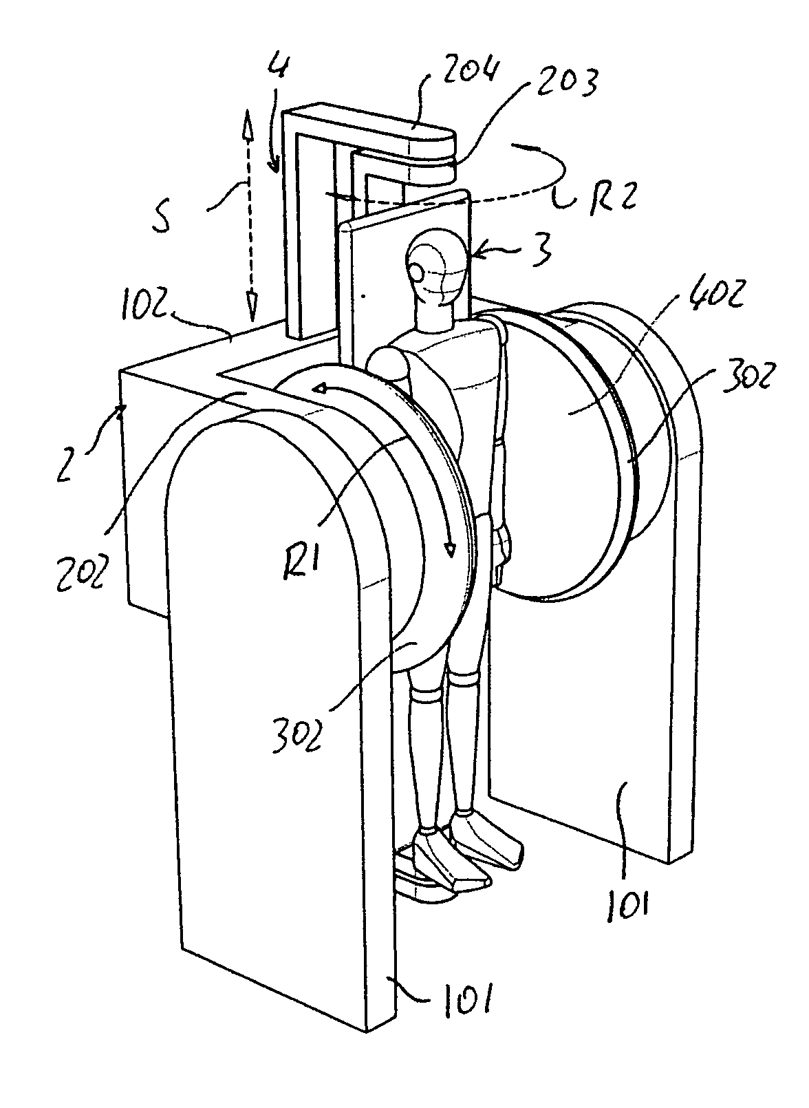
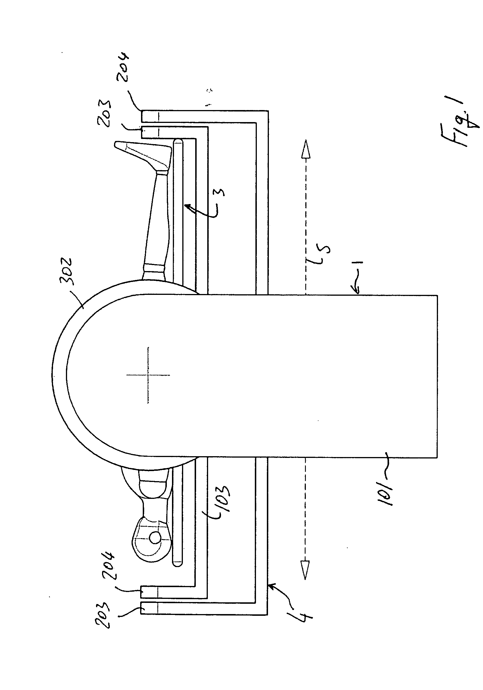
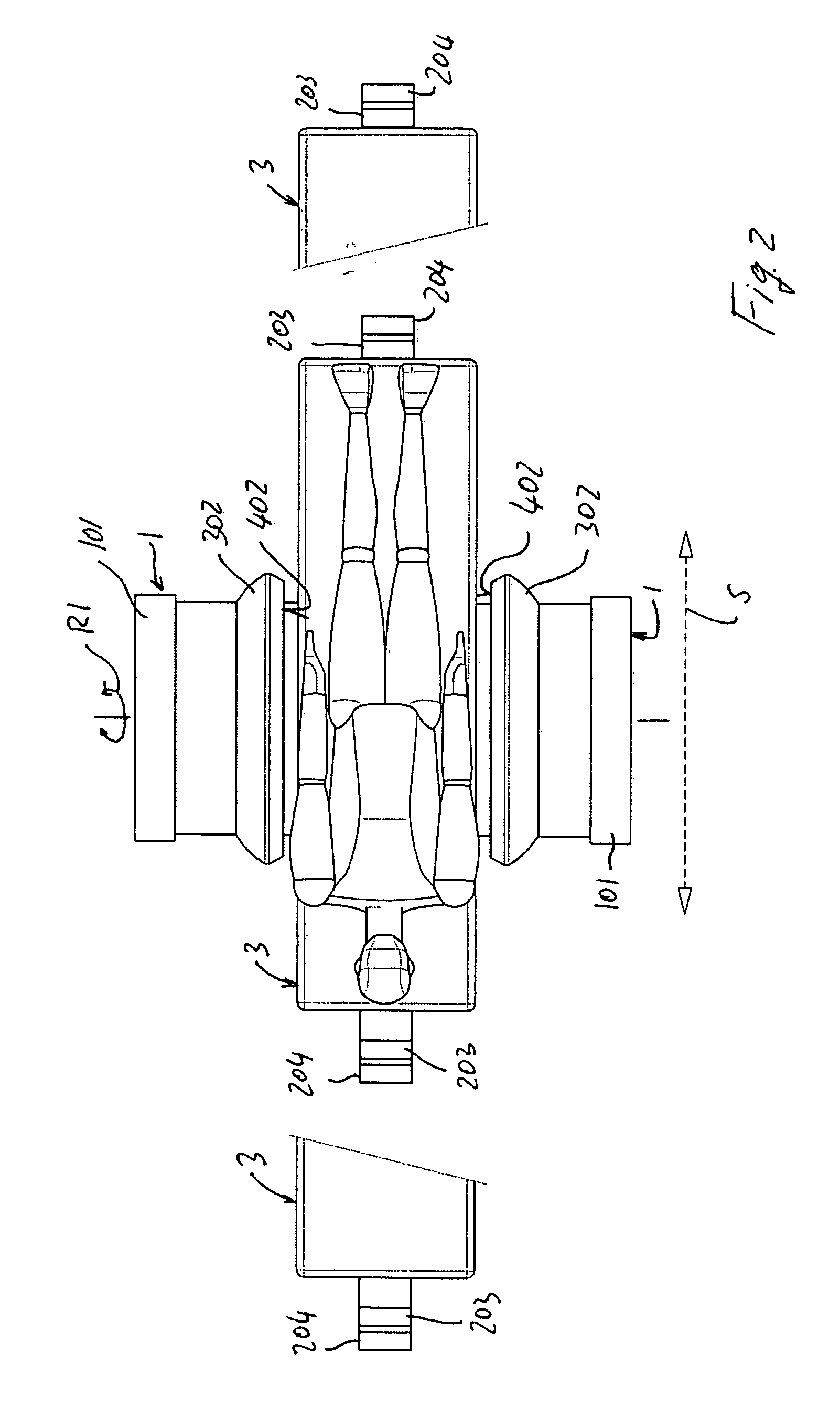
[0203] An embodiment of an MRI imaging apparatus according to the present invention is schematically illustrated in FIGS. 1 to 9.

[0204] The MRI apparatus comprises a supporting basement 1 which is formed by two parallel vertical walls 101 which are spaced apart one from the other. Between the two vertical walls 101 a magnetic structure 2 is provided. The magnetic structure 2 is formed by an U-shaped yoke which is supported by the basement 1 between the two vertical walls 101. The U shaped yoke has a central transverse branch 102 and two lateral parallel branches 202. The central branch 102 is oriented horizontally and transversely to the two vertical walls of the supporting basement 1 and connects the two lateral branches 202 which lay in planes parallel to the two opposite vertical walls 101 of the supporting basement 1. At its the free end each lateral branch 202 of the U-shaped yoke bears a magnetic pole 302. The two magnetic poles are facing each other, being spaced apart one f...


PUM


Abstract

A magnetic resonance imaging apparatus including a magnetic structure having two opposite and spaced apart poles and a column or wall transverse to the poles and connecting the poles; the poles defining two opposite walls delimiting a patient-imaging space, the two opposite walls extending along substantially parallel planes which are substantially parallel to a vertical plane; and a patient positioning table which is slidably connected to a supporting frame between the two poles; the table being positioned with its longitudinal axis substantially parallel to the two opposite parallel walls of the poles and the table being oriented with its transverse axis perpendicular to at least one of the two opposite walls.

Description

BACKGROUND OF THE APPLICATION [0001] 1. Field of the Invention [0002] The invention relates to a magnetic resonance imaging apparatus, and particularly to a multipurpose dedicated imaging apparatus having improved features for imaging the region of the vertebral column under different load conditions. [0003] 2. Description of the Related Art [0004] Imaging the vertebral column may require the possibility of bringing the patient in an upright position in order to have the vertebral column loaded by the weight of the patient. In the normal laying down position of the patient on a bed or table having an horizontal orientation, the vertebral column will be in an unloaded and ideal condition. Thus, most pathologies may not arise clearly and the examination will lead to unclear results or to negative results despite the fact that the patient is showing typical symptoms of a disease of the vertebral column. [0005] Most spinal disease can be best evaluated by imaging the anatomic region wit...

Claims


Application Information

Patent Timeline
IPC IPC(8): G01R33/28
CPCG01R33/3806A61B5/055A61B5/704
Inventor TREQUATTRINI, ALESSANDROREZZONICO, FABIOBIGLIERI, EUGENIOSATRAGNO, LUIGI
Owner ESAOTE
Learn More