
Magnetic device, skyrmion memory, skyrmion memory-device, solid-state electronic skyrmion-device, data-storage device, data processing and transferring device

a technology of memory elements and magnetic devices, applied in the field of magnetic elements, can solve the problems of low transfer velocity of magnetic domain walls, low transfer velocity of skyrmions in longitudinal transfer arrangement, and increase and achieve the effect of increasing the transfer velocity of skyrmions, small magnetic structure, and increasing the expectation of skyrmions being used in memory elements

Active Publication Date: 2017-06-15
RIKEN
View PDF1 Cites 8 Cited by
  • Summary
  • Abstract
  • Description
  • Claims
  • Application Information

AI Technical Summary

Benefits of technology

The patent text explains a technology that lets people make calls over the internet. This technology makes it easier for people to make calls without needing a landline or cell phone.

Problems solved by technology

However, this type of magnetic shift register 1 requires a large current when moving the magnetic domain walls, and there is a disadvantage that the transfer velocity of the magnetic domain walls is low.
Furthermore, in the case of a nano-size domain, a problem occurs that spin reversal occurs due to thermal disturbance.
However, it became clear that there was a major problem that the transfer velocity of the skyrmions is low in the longitudinal transfer arrangement (see Non-Patent Document 2).
As a second issue to be addressed, there is a problem that the skyrmion drive current density is large in the longitudinal transfer arrangement.
When handling the skyrmions as information units, it was made clear that there is a problem of the transfer velocity of the skyrmions is slow, and therefore that the current density for driving is large.

Method used


Image

  • Magnetic device, skyrmion memory, skyrmion memory-device, solid-state electronic skyrmion-device, data-storage device, data processing and transferring device
  • Magnetic device, skyrmion memory, skyrmion memory-device, solid-state electronic skyrmion-device, data-storage device, data processing and transferring device
  • Magnetic device, skyrmion memory, skyrmion memory-device, solid-state electronic skyrmion-device, data-storage device, data processing and transferring device

Examples


first embodiment example

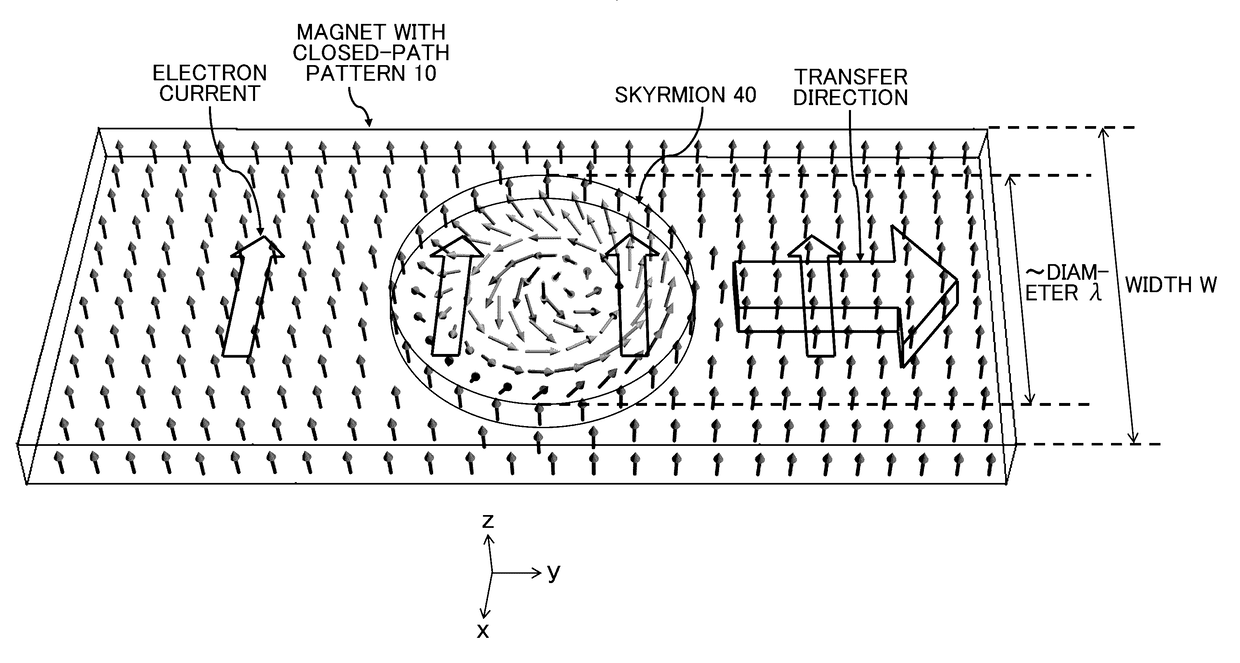
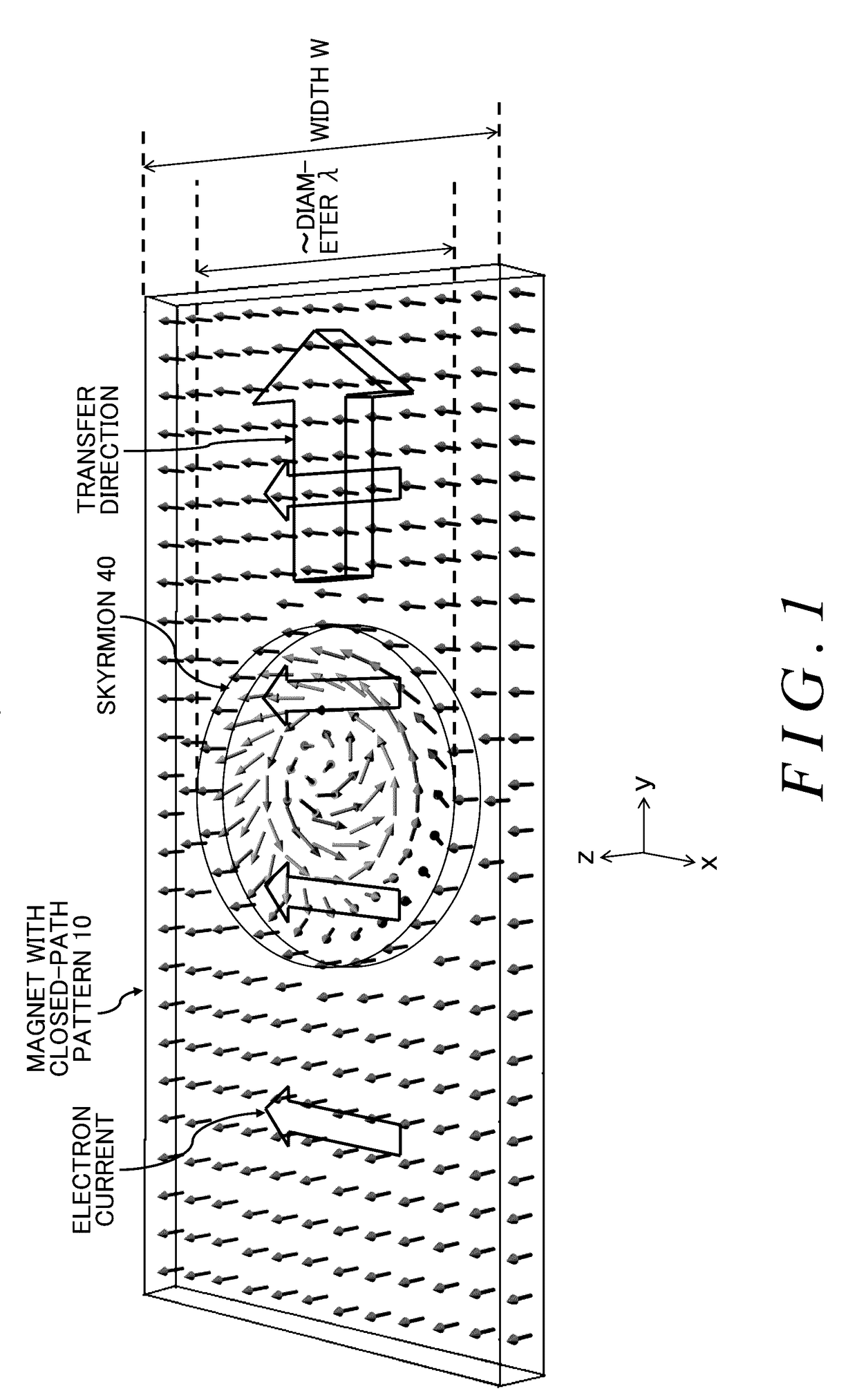
[0145]In the first embodiment example, simulation experiment results of the generation and transfer of a skyrmion are shown. The motion of the magnetic moment of the skyrmion can be expressed with the motion equation shown in Expression 8. The following shows a numerical solution of the equations shown below, which include terms for adiabatic and non-adiabatic spin transfer torque.

dMr / dt=−Mr×Breff+α / M·Mr×dMr / dt+pa3 / 2eM(j(r)·∇)Mr−(pa3β / (2eM2)[Mr×(j(r)·∇)Mr]  Expression 8 :

H=−JΣMr·(Mr+ex+Mr+ey)−DmΣ(Mr×Mr+ex·ex+Mr×Mr+ey·ey)−B·ΣMr   Expression 9:

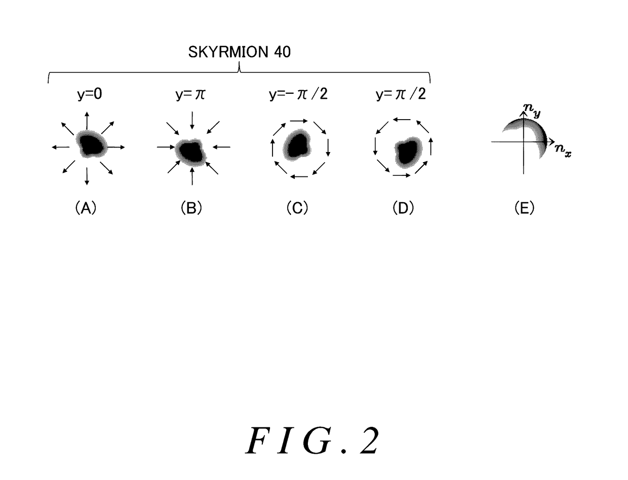
[0146]Here, as a result of Breff=−(1 / (hγ))(∂H / ∂Mr), Expression 8 and Expression 9 are associated with each other. Furthermore, γ=gμB / h (>0) is the magnetic rotation ratio, h is the Planck constant, Mr=M·n(r), Mr indicates the magnetic moment, n(r) is the unit vector indicating the orientation of the magnetic moment of the skyrmion 40 at the position r shown in Expression 2, and ×indicates the cross product in Expression 8 and Expression 9 above....

second embodiment example

[0172]Next, FIGS. 13 to 17 show the simulation results of the deletion of a skyrmion formed in the skyrmion memory circuit of the magnet 10 with the closed-path pattern. Furthermore, in the same manner as in the first embodiment example, in the example of FIGS. 13 to 17, the size of the end region surrounded by the first current path 16-1 is such that the width W1 is 0.75λ and the length L1 is 0.5λ. The second embodiment example corresponds to the times after the time t=50000(1 / J) shown in FIG. 6.

[0173]FIG. 13 shows a state at t=58100(1 / J). The four skyrmions generated in FIG. 12 are circulating stably.

[0174]FIG. 14 shows a state at t=83150(1 / J). One skyrmion 40 reaches the first current path 16-1. A first current path power supply 50 begins making the coil current for deletion flow at t=83150(1 / J). In the present example, the orientation of the coil current for deletion is the same as the orientation of the coil current for generation of the skyrmion 40. Furthermore, the peak value...

third embodiment example

[0187]The simulation results of FIGS. 18 and 19 show that a plurality of skyrmions 40 in the skyrmion memory circuit of the magnet 10 with the closed-path pattern can be deleted en masse by the current between the outer circumference electrode 12 and the inner circumference electrode 14 in the transverse transfer arrangement. FIG. 18 shows an example of the current density of the current flowing through the magnet 10 with the closed-path pattern from the outer circumference electrode 12 in the direction of the inner circumference electrode 14. In the present example, the current density for the circular transfer by which the skyrmions 40 circulate in the skyrmion memory circuit 30 of the magnet 10 with the closed-path pattern is 0.001ξj. When deleting the skyrmions 40 en masse, the current density of the current flowing through the magnet 10 with the closed-path pattern is further raised from a current density of 0.001ξj, which is necessary for the transmission in the transverse tra...


PUM


Abstract

Provided is a skyrmion memory circuit capable of circularly transferring a magnetic element skyrmion, comprising one or more current paths in a magnet having a closed-path pattern that are provided surrounding an end region including an end portion of the magnet in a plane of the magnet with the closed-path pattern, and applying current between an outer terminal connected to an outer circumferential portion of the closed-path pattern and an inner circumference electrode connected to an inner circumferential portion of the closed-path pattern, transferring the skyrmion in a direction substantially perpendicular to the direction of the applied current, and circulating the skyrmion in the magnet with the closed-path pattern.

Description

[0001]The contents of the following Japanese patent applications are incorporated herein by reference:[0002]NO. 2014-139030 filed in JP on Jul. 4, 2014 and[0003]NO. PCT / JP2015 / 068888 filed on Jun. 30, 2015.BACKGROUND[0004]Technical Field[0005]The present invention relates to a magnetic element using skyrmions as a memory, a skyrmion memory, a skyrmion memory circuit, a skyrmion memory device, a skyrmion-memory-device embedded solid-state electronic device, a data recording apparatus, a data processing apparatus, and a communication apparatus.[0006]Related Art[0007]A magnetic element is known that uses the magnetic moment of a magnet as digital information. A skyrmion memory using skyrmions, which is a magnetic element, includes the element structure of a nonvolatile memory that does not require power when holding nanoscale information. Based on advantages such as ultra-high density resulting from the nanoscale magnetic structure, this magnetic element is expected to be used as a hig...

Claims


Application Information

Patent Timeline
Patent Type & Authority Applications(United States)
IPC IPC(8): G11C19/08
CPCG11C19/0866G11C19/085H01F10/08G11C11/16G11C11/1673G11C11/18G11C19/0841G11C19/0858G11C11/1675G11C11/5657H10N50/10G11C11/161H01L27/105
Inventor NAGAOSA, NAOTOKOSHIBAE, WATARUIWASAKI, JUNICHIKAWASAKI, MASASHITOKURA, YOSHINORIKANEKO, YOSHIO
Owner RIKEN
Learn More