
Microsensor catheter and method for making the same

a microsensor and catheter technology, applied in the field of biomedical technology, can solve the problems of inability to accurately measure tissue perfusion, low production capacity, and inability to meet the needs of patients with indwelling arterial catheters, and achieve the effect of easing production capacity and lessening difficulties

Inactive Publication Date: 2005-08-25
CHILDRENS HOSPITAL MEDICAL CENT CINCINNATI
View PDF10 Cites 107 Cited by
  • Summary
  • Abstract
  • Description
  • Claims
  • Application Information

AI Technical Summary

Benefits of technology

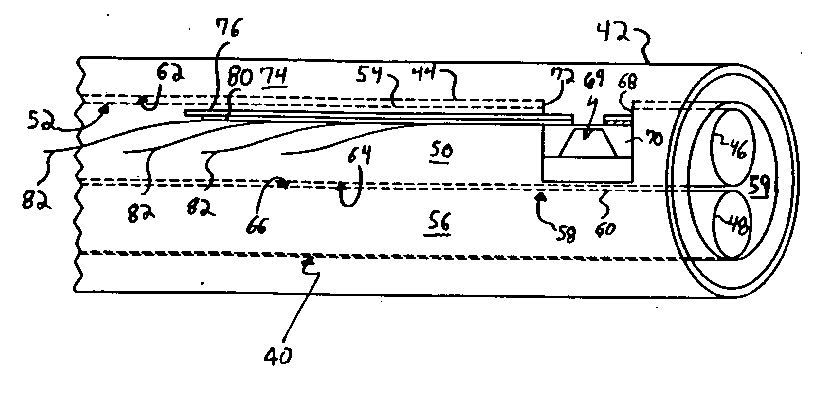
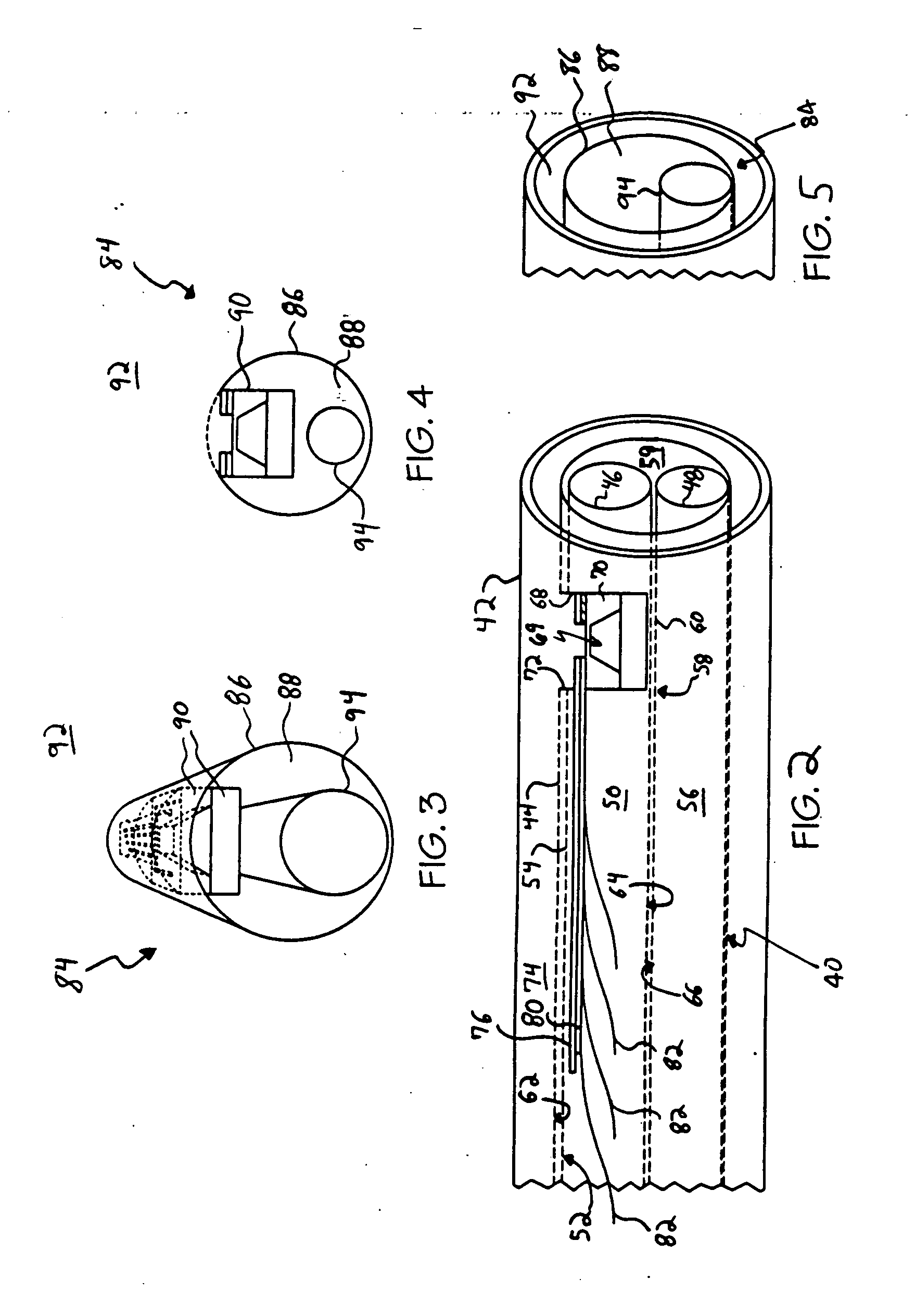
[0013] Each microsensor device may be mounted to a flexible substrate prior to being mounted to or within a catheter or a tube. In exemplary embodiments, the flexible substrate is in the form of an elongated strip or ribbon of dielectric materal, where the microsensor device is mounted approximate the leading end of the strip. While the present invention is discussed herein as utilizing an exemplary flip-chip bonding technique, the use of such technique is not required, as those of ordinary skill, particularly in the semiconductor fields, are familiar with means for mounting a chip onto conductive leads. The flexible dielectric substrate includes electrical leads for bonding to the microsensor device, and may also include electrical leads connected to the display and / or data acquisition device. While such leads may be coupled to the display and / or data acquisition device, it is also envisioned that such microsensor devices communicate wirelessly with the display or data acquisition device using appropriate RF components. By mounting the microsensor devices to the flexible dielectric substrate, the combination of such eases the production capabilities and lessens the difficulties of mounting such microsensor devices within the catheter or tube.

Problems solved by technology

The current monitoring capacity and capabilities are very crude for this group of patients.
Current methodology to measure tissue perfusion, blood flow and pressures are extremely primitive and cumbersome.
Those patients that have indwelling arterial catheters may risk significant complications associated with the placement of these monitoring devices.
Neonates requiring critical care are often transfused on a regular basis since blood drawn for tests may induce anemia.

Method used


Image

  • Microsensor catheter and method for making the same
  • Microsensor catheter and method for making the same
  • Microsensor catheter and method for making the same

Examples


Embodiment Construction

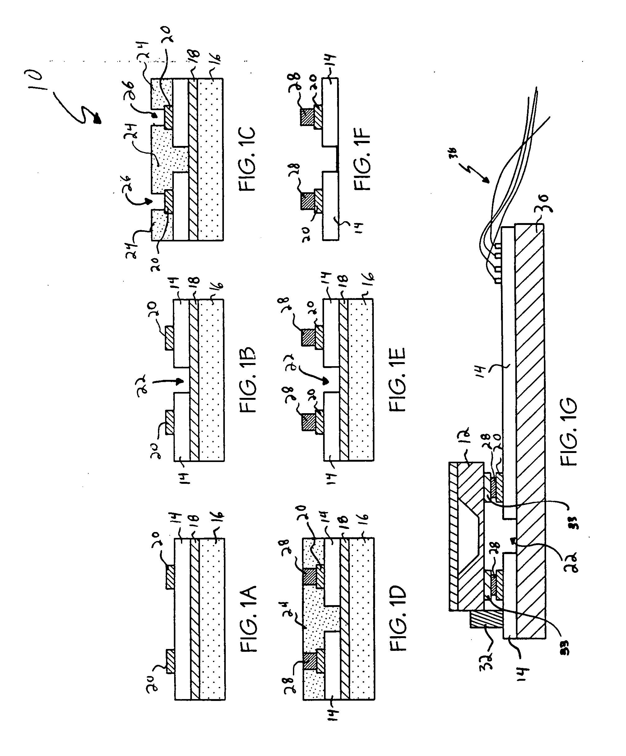
[0037] The exemplary embodiments of the present invention are described and illustrated below to encompass methods of mounting microsensors onto a flexible substrate, and catheters incorporating such microsensors mounted to a flexible substrate adapted to be utilized as a neonatal diagnostic apparatus. Of course, it will be apparent to those of ordinary skill in the art that the preferred embodiments discussed below are exemplary in nature and may be reconfigured without departing from the scope and spirit of the present invention. However, for clarity and precision, the exemplary embodiments as discussed below may include optional steps and / or features that one of ordinary skill should recognize as not being a requisite to fall within the scope and spirit of the present invention.

[0038] Referencing FIGS. 1A-1G, an exemplary flip-chip bonding process 10 will be described for mounting a microsensor device 12 onto a substrate 14 prior to the substrate being mounted to a catheter or a...


PUM


Abstract

A catheter for insertion into a body cavity, duct, or vessel for diagnostic purposes, the catheter including a flexible conduit having a microsensor device mounted thereto that generates output data from a sensed condition. The microsensor device is operatively coupled to a data acquisition device to communicate the output data to the data acquisition device. The microsensor device is mounted to a flexible dielectric substrate carrying a lead, and the flexible dielectric substrate is separate from and carried by the flexible conduit.

Description

CROSS-REFERENCE TO RELATED APPLICATION [0001] This application claims priority to and benefit of Provisional Application No. 60 / 538,549, filed on Jan. 23, 2004, which is herein incorporated by reference in its entirety.BACKGROUND [0002] 1. Field of the Invention [0003] The present invention is directed to biomedical technology intended for enhancing the care and treatment of patients, and more specifically to a physiologic monitor or catheter that may be utilized in the diagnosis and / or treatment of neonatal patients by transmitting real-time information to a data acquisition device. [0004] 2. Background of the Invention [0005] Intravascular blood pressure measurements in patients are most commonly performed using a saline filled pressure transferring catheter and external pressure sensors. By measuring the pressure with a miniature sensor inside the artery, time response and accuracy can be improved. [0006] There are a number of approaches used to measure pressure and flow with mic...

Claims


Application Information

Patent Timeline
IPC IPC(8): A61B5/00A61B5/02A61B5/0215A61B5/026A61M25/16A61M25/18
CPCA61B5/01A61B5/0215A61B5/026A61B2560/0242A61B5/14539A61B5/6851A61B5/14532
Inventor AZIZKHAN, RICHARD G.PAPAUTSKY, IANAHN, CHONG H.
Owner CHILDRENS HOSPITAL MEDICAL CENT CINCINNATI
Learn More