[0008] By utilizing the existing pedal
system and linking its various components, weight, complexity and cost are reduced. And in cases where the bicycle offers multispeed gearing, this method offers the additional
advantage of being able to link these gears to the motor and to the pedals. Multispeed gearing enhances the performance of the
electric bicycle. As a retrofit or “kit”, or as an original manufacture, the existing pedal system and gears are linked with the motor.
[0009] By integrating the existing pedal system with the motor and by linking the various pedal components with the motor, performance of the
electric bicycle is significantly enhanced. Existing electric bicycles have difficulty climbing hills or grades. By integrating the existing pedal components and especially multispeed gearing, this method benefits from these gears being used as a transmission to allow enhanced ascent of hills or grades. No other “kit” utilizes this method. In this separate aspect of the invention, an
electric motor provided in a kit drives the rear wheel(s) of the bicycle through the existing
gear system on the bicycle. Consequently, there is less need to match the torque characteristics of the motor over the entire load range.
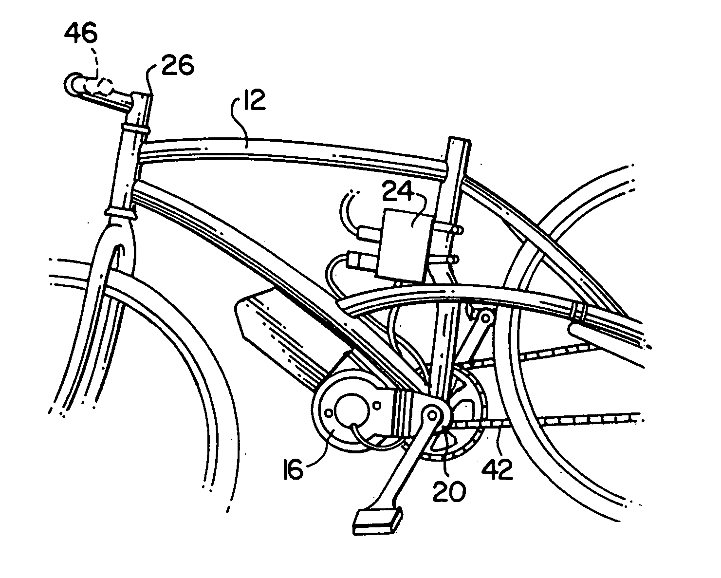
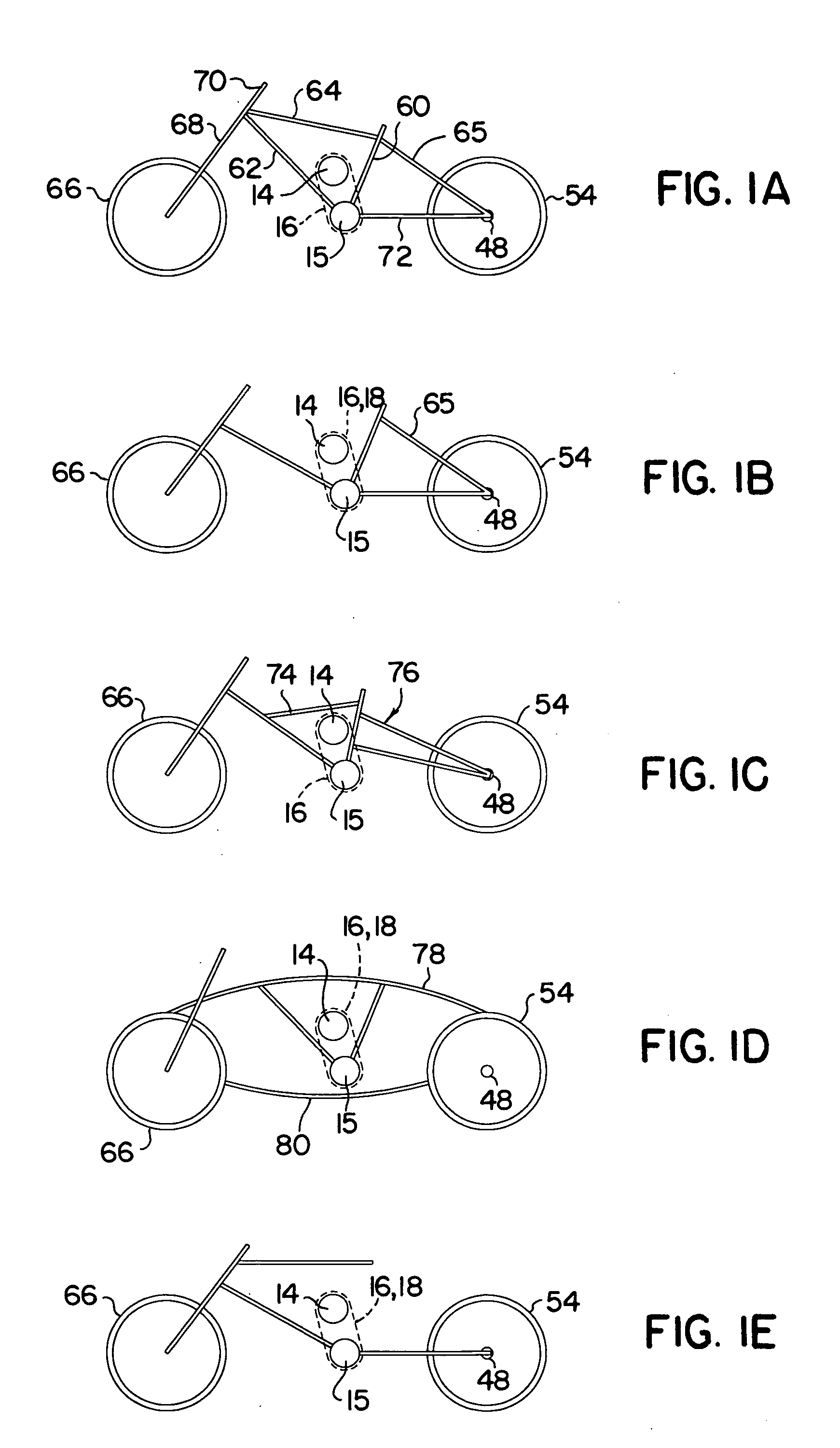
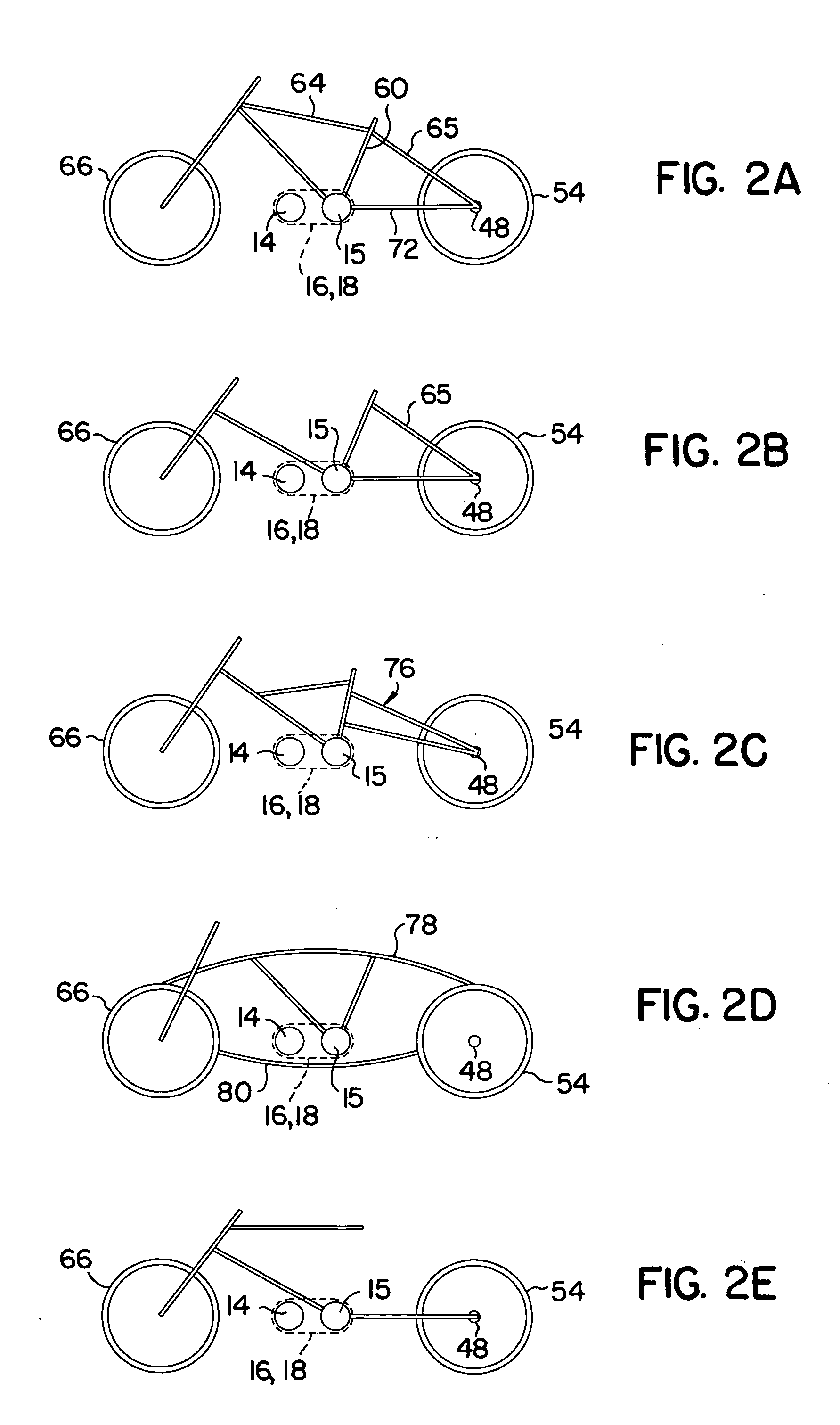
[0010] A method for attaching the kit to the frame includes plates or brackets that hold or sandwich the motor between the bottom bracket. The set of plates or brackets holding the motor are also preferably secured to the bicycle frame at the bottom bracket end. The plates or brackets position the motor between the bottom bracket ends and a clamp also attaches the motor to a down tube, cross tube, seat tube or any other location that prevents the motor from rotating when torque is exerted on the pedals by the operator or when torque is exerted when the motor is engaged. The plates or brackets hold the motor in place and also position the motor to align the motor
sprocket with the drive chain. By tightening the bottom bracket nuts, the motor plates or brackets are tightened against the bicycle frame which in turn secures the
motor system to the bicycle. (This allows for a retrofit, or “kit” methodology). This method eliminates the need for specially designed frames, permanent mounting methods, and permanent or welded fixtures. The bicycle owner can therefore remove the kit from one bicycle and install the kit onto another bicycle. In this separate aspect of the invention, the mounting plates allow the electric motor to be added onto an ordinary bicycle, using common tools, and without the need to modify the bicycle via
welding, etc.
[0011] The set of plates or brackets holding the motor are also preferably positioned in such a way as to align the motor output
sprocket with the driven wheel sprocket and the pedal chainwheel. The motor plates are designed to accommodate any bottom bracket end dimension and or any bottom bracket end type, including
cartridge or open bearing spindle variety. In this separate aspect of the invention, alignment of the sprockets is maintained, avoiding premature wear on the sprockets and chains (or equivalent drive means such as belts and pulleys). The motor is preferably located at or near a low point of the bicycle, so that the weight of the motor is optimized relative to the bicycle center of gravity. In this separate aspect of the invention, bicycle stability and handling are improved. The battery may also be located at a low point, near or on the motor.
[0013] In another separate aspect of the invention, an electrically or electronically actuated circuit,
relay or mechanical switch momentarily interrupts
motor power to the driven wheel. This is useful because continuous and moderate to high power at the rear or driven wheel during e.g.,
hill climbing or under heavy loading, makes shifting difficult or impossible (at least with most bicycle gearing systems). The system interrupts the
motor power for a duration long enough to allow the bicyclist to shift gears without decelerating. This allows the bicyclist to maintain maximum forward
momentum. The system preferably senses either motor current draw or torque on the drive sprocket or chain, and also senses
initiation of gear shifting. Upon sensing the presence or threshold values of gear shift
initiation alone, or gear shift
initiation together with a motor condition (such as current or torque) the system reduces or stops current to the motor for a selected time interval. The time interval is sufficient to allow for completion of gear shifting, typically from 0.5-5 or 1, 2, or 3 seconds. The system may select from a table of interval values, or calculate an interval value, based on sensed input parameters including present gear condition, shift direction (up or down), pedal speed, bicycle speed or wheel rpm, torque loading, inclination angle, weight, etc. Sensors for detecting these parameters may be included and linked into the system, typically in a
microprocessor or similar device in the
motor controller.
[0014] The integration of motor with pedal drive components offers the
advantage of reducing complexity, weight, and cost while increasing performance and battery efficiency. If the bicycle has multispeed gears, this method can utilize these gears to enhance the torque and / or speed of the motor.

