Electrode wire for wire electric discharge machining

a technology of electrode wire and electric discharge, which is applied in the direction of electrical-based machining electrodes, welding apparatus, manufacturing tools, etc., can solve the problems of increasing the manufacturing cost of electrode wires, not necessarily sufficient from the viewpoint of machining speed, and the inability to substantially perform wire drawing without electrode wires. , to achieve the effect of increasing cos

Inactive Publication Date: 2005-09-01
SAN ETSU METALS
View PDF8 Cites 10 Cited by
  • Summary
  • Abstract
  • Description
  • Claims
  • Application Information

AI Technical Summary

Benefits of technology

[0015] However, the addition of such an additional element not only increases cost, but also poses a recyclability problem from the viewpoint of electrode wire wastes.
[0018] wherein α phase crystals and β′ phase crystals uniformly exist.
[0022] hot-

Problems solved by technology

An electrode wire made of a binary alloy of copper and zinc with a zinc content of 35 to 40% is comparatively inexpensive, but is not necessarily sufficient from the viewpoint of the machining speed and the characteristics when causing a workpiece to be melted and cut.
However, since the electrode wire having a multilayer structure has a complicated structure, manufacturing cost of the electrode wire is increased to a large extent.
However, wire drawing cannot be substantially performed without adding an additional element s

Method used


Image

  • Electrode wire for wire electric discharge machining
  • Electrode wire for wire electric discharge machining
  • Electrode wire for wire electric discharge machining

Examples


example 1

[0056] Examples of the electrode wire for wire electric discharge machining of the present invention are described below in detail.

[0057] Copper and zinc ingots were dissolved, and an alloy was produced so that the average zinc content per unit volume was 42.5%.

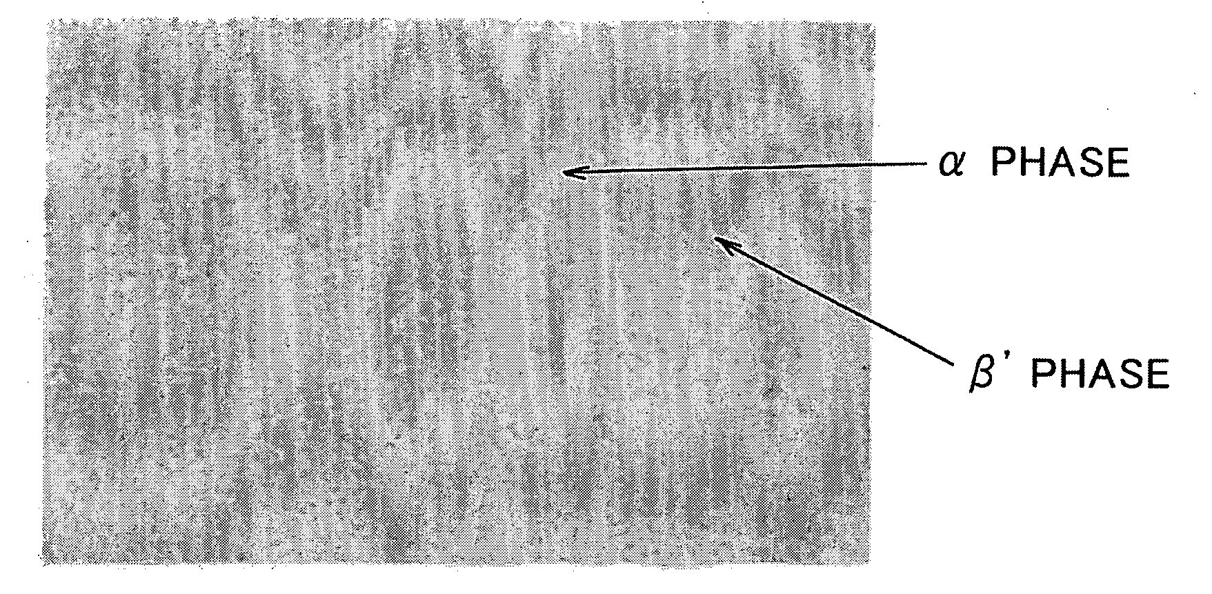
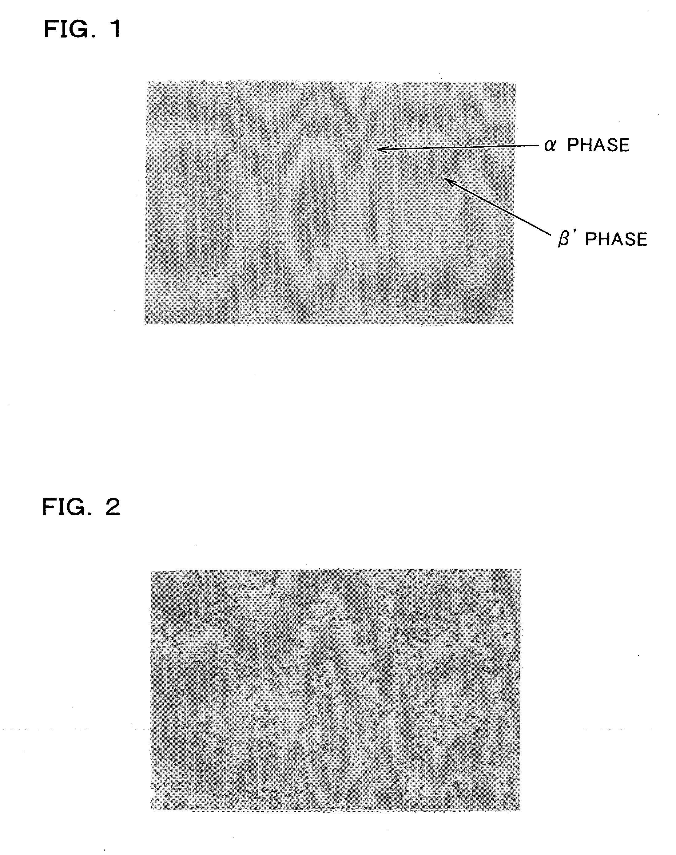
[0058] The resulting copper-zinc alloy was hot-extruded while taking crystal growth into consideration, and repeatedly subjected to cold drawing and annealing in stages while reducing the amount of precipitated β phase and nonuniform dispersion to obtain an alloy wire with a diameter of φ 0.9 mm.

[0059] The resulting alloy wire was cold-drawn to a diameter of φ 0.25 mm and 0.30 mm using a continuous slip drawing machine.

[0060] The resulting alloy wires were subjected to final electric annealing to obtain electrode wires of the present invention and reference electrode wires shown in Table 1.

[0061] The electrode wires of the present invention shown in Table 1 are examples in which the electrode wires are drawn to a final d...

example 2

[0063] Copper and zinc ingots were dissolved, and alloys were produced so that the average zinc content per unit volume was 43.0% and 42.0%. Electrode wires of the present invention with a diameter of 0.25 mm were produced in the same manner as in Example 1.

[0064] The electrode wires of Example 1, Example 2, and Reference Example 1, and electrode wires containing only the α phase and having a zinc content of 37% as conventional electrodes were installed in a wire electric discharge machine (“RA90AT” manufactured by Mitsubishi Electric Corporation). The machining speed when machining a die steel (SKD-11) with a thickness of 50 mm under standard setting conditions was measured.

[0065] The tensile strength was also measured using a tensile tester.

[0066] Table 1 shows the target Zn content of the electrode wires of the present invention and the reference electrode wires, the speed ratio with respect to the conventional electrodes (100%), the tensile strength, and wire evaluation resul...


PUM

PropertyMeasurementUnit
Fractionaaaaaaaaaa
Tensile strengthaaaaaaaaaa

Abstract

An electrode wire for wire electric discharge machining includes a binary alloy of copper and zinc. The electrode wire is manufactured by hot-extruding an alloy including copper and zinc at a predetermined ratio and then cold-drawing and annealing the hot-extruded alloy, and α phase crystals and β′ phase crystals uniformly exist.

Description

[0001] Japanese Patent Application No. 2004-37602, filed on Feb. 16, 2004, is hereby incorporated by reference in its entirety. BACKGROUND OF THE INVENTION [0002] The present invention relates to an electrode wire for wire electric discharge machining. [0003] More particularly, the present invention relates to an electrode wire for wire electric discharge machining which allows a workpiece to be melted and cut at high speed when causing an electric discharge to occur between the wire and the workpiece, exhibits higher productivity in comparison with a conventional high-speed electrode wire, and has excellent recyclability. [0004] Wire electric discharge machining is a machining method which causes a workpiece to be melted and cut by causing an electric discharge phenomenon to occur between an electrode wire for wire electric discharge machining and the workpiece. [0005] Since this machining method enables machining such as that using a fretsaw, this machining method is particularly ...

Claims


Application Information

Patent Timeline
IPC IPC(8): B23H1/04B23H1/06B23H7/08C22C9/04C22F1/00C22F1/08
CPCB23H7/08B21C23/08C22C9/04B23H1/04
Inventor KAWAMOTO, YOSHIAKIMORIYAMA, ETSURO
Owner SAN ETSU METALS
Why Eureka
Try Eureka