Optical receiver comprising a receiver photodetector integrated with an imaging array

a technology of optical receiver and imaging array, applied in the field of optical communication systems with line of sight, can solve the problems of reducing or losing signals that can substantially impair communication, unable to meet the requirements of the full potential of the lsoc system, and none of them have been completely satisfactory, and achieve the effect of high speed

Inactive Publication Date: 2005-09-01
INFRARED NEWCO
View PDF31 Cites 27 Cited by
  • Summary
  • Abstract
  • Description
  • Claims
  • Application Information

AI Technical Summary

Benefits of technology

[0011] In accordance with the invention, an optical communication system is provided with an optical receiver cell integrated at the center of a two-dimensional imaging array (imager). The combined receiver and imager carries out both photodetection (converting photons to electrons), and circuit functions (e.g. amplifying and integrating the signals from the photodetectors). The receiver cell advantageously comprises a high speed photodetector and a high-speed amplification circuit, that prov

Problems solved by technology

One difficulty that has delayed the full potential of LSOC systems is the necessity that the receiver and transmitter be very accurately pointed at one another to establish the desired link.
Any loss of pointing accuracy leads to a reduction or loss of signal that can substantially impair communication.
While there have been a variety of approaches to achieving the desired accuracy, none have proven completely satisfactory.
This approach, however, adds extra hardware to the system and requires human intervention.

Method used


Image

  • Optical receiver comprising a receiver photodetector integrated with an imaging array
  • Optical receiver comprising a receiver photodetector integrated with an imaging array
  • Optical receiver comprising a receiver photodetector integrated with an imaging array

Examples


Embodiment Construction

[0021] One aspect of the present invention is an integrated receiver and imager for a line-of-sight optical communication systems (LSOC). The integrated receiver and imager is intended to be used in a LSOC at the heart of the receiving system.

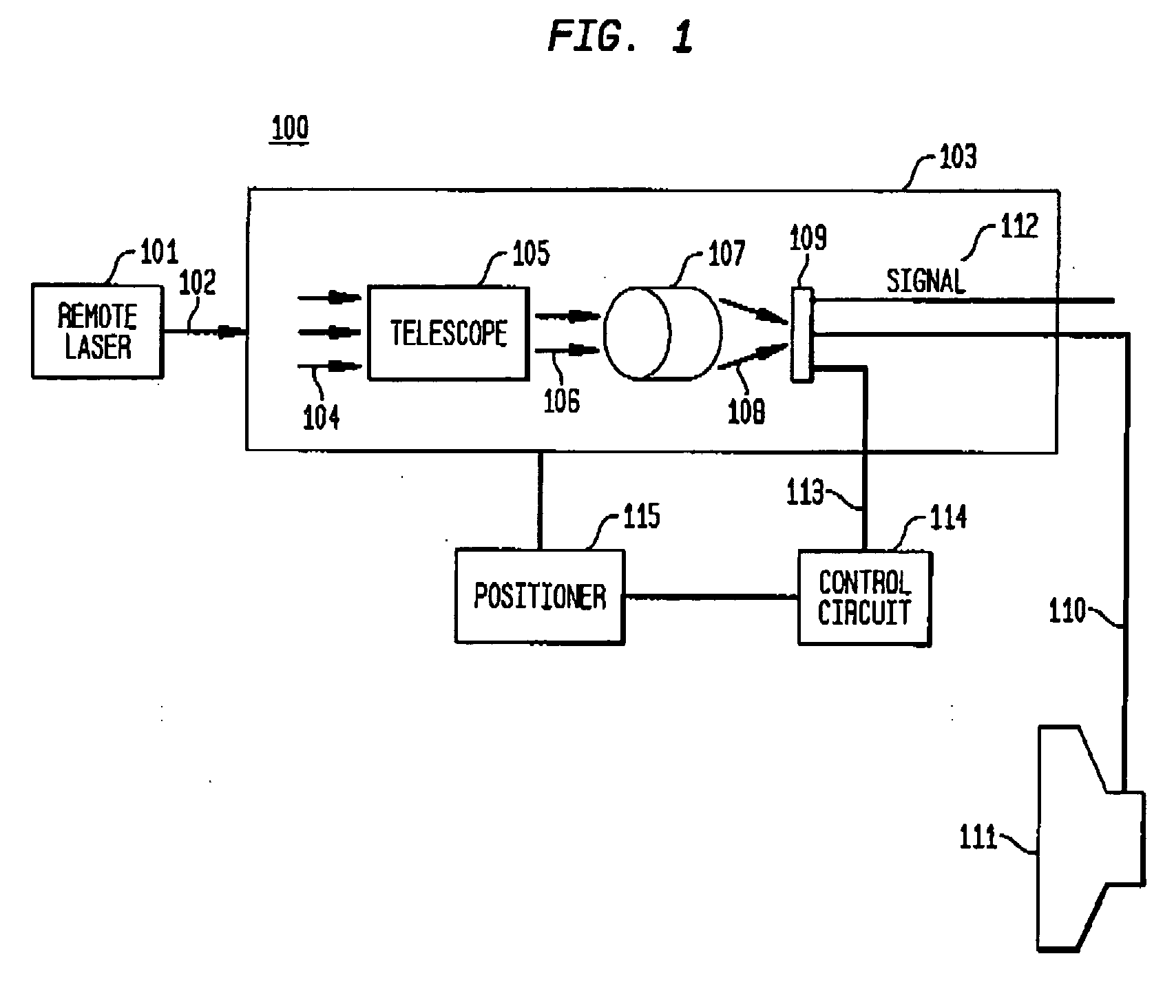
[0022] Referring to the drawings, FIG. 1 schematically illustrates a LSOC 100 using an integrated receiver and imager in accordance with the invention. The system comprises a remote optical transmitter 101, such as a modulated laser, that can shine a beam of light 102 through atmosphere or space onto an optical receiver 103. At the receiver, the transmitted beam 104 will be collected by collection optics (e.g. telescope 105) and concentrated to a smaller beam 106 that falls on a variable focal length lens 107. The variable lens 107 can either pass the beam with spot size unchanged (collimated beam), or it can focus the beam (converging beam 108). Whether collimated or converging, the beam falls on the integrated receiver and imager 109. When t...


PUM


Abstract

A high-speed optical communications cell is integrated at the interior of a two-dimensional imaging array. The combined receiver and imager carries out both photodetection (converting photons to electrons) and circuit functions (e.g. amplifying and integrating the signals from the photodetectors). The high-speed receiver cell comprises a photodetector and a high-speed amplification circuit, providing an electrical output which can follow a rapidly varying optical signal falling on the photodetector. The imaging array comprises an array of photodetectors and readout circuits, providing an electrical representation of the variation of light with position across the receiver surface. The presence of an imaging array surrounding the communications receiver, and in the same plane as it, allows a single optical path to be used for source acquisition and tracking as well as for data reception

Description

CROSS REFERENCES TO RELATED APPLICATIONS [0001] This application claims the benefit of U.S. Provisional Application Ser. No. 60 / 510,933 filed by Conor S. Rafferty and Clifford A. King on Oct. 13, 2003 and entitled “Communications Photodetector Integrated With Imaging Array”, which application is incorporated herein by reference.FIELD OF THE INVENTION [0002] This invention relates to line-of-sight optical communication systems and, in particular, to a receiver integrated with an imaging array for such optical communication and related systems. BACKGROUND OF THE INVENTION [0003] Line-of-sight optical communication systems (LSOCs) are becoming increasingly important in a wide variety of applications. A typical LSOC comprises a laser transmitter for transmitting a modulated narrow beam of light through space or the Earth's atmosphere to a photodetector receiver. In space, line-of-sight optical communication to and from satellites is generally faster than radio communication and uses lig...

Claims


Application Information

Patent Timeline
IPC IPC(8): H04B10/06H04B10/118
CPCH04B10/118
Inventor RAFFERTY, CONOR S.KING, CLIFFORD ALAN
Owner INFRARED NEWCO
Why Eureka
Try Eureka