
Hydrogen fire detection system & method

a technology for fire detection and apparatus, applied in fire alarms, optical radiation measurement, instruments, etc., can solve the problems of not all flames producing significant quantities of carbon dioxide, exhibiting relatively strong emissions, and reducing the sensitivity of conventional carbon dioxide spectrum flame detectors

Active Publication Date: 2005-09-08
DETECTOR ELECTRONICS CORP
View PDF7 Cites 17 Cited by
  • Summary
  • Abstract
  • Description
  • Claims
  • Application Information

AI Technical Summary

Problems solved by technology

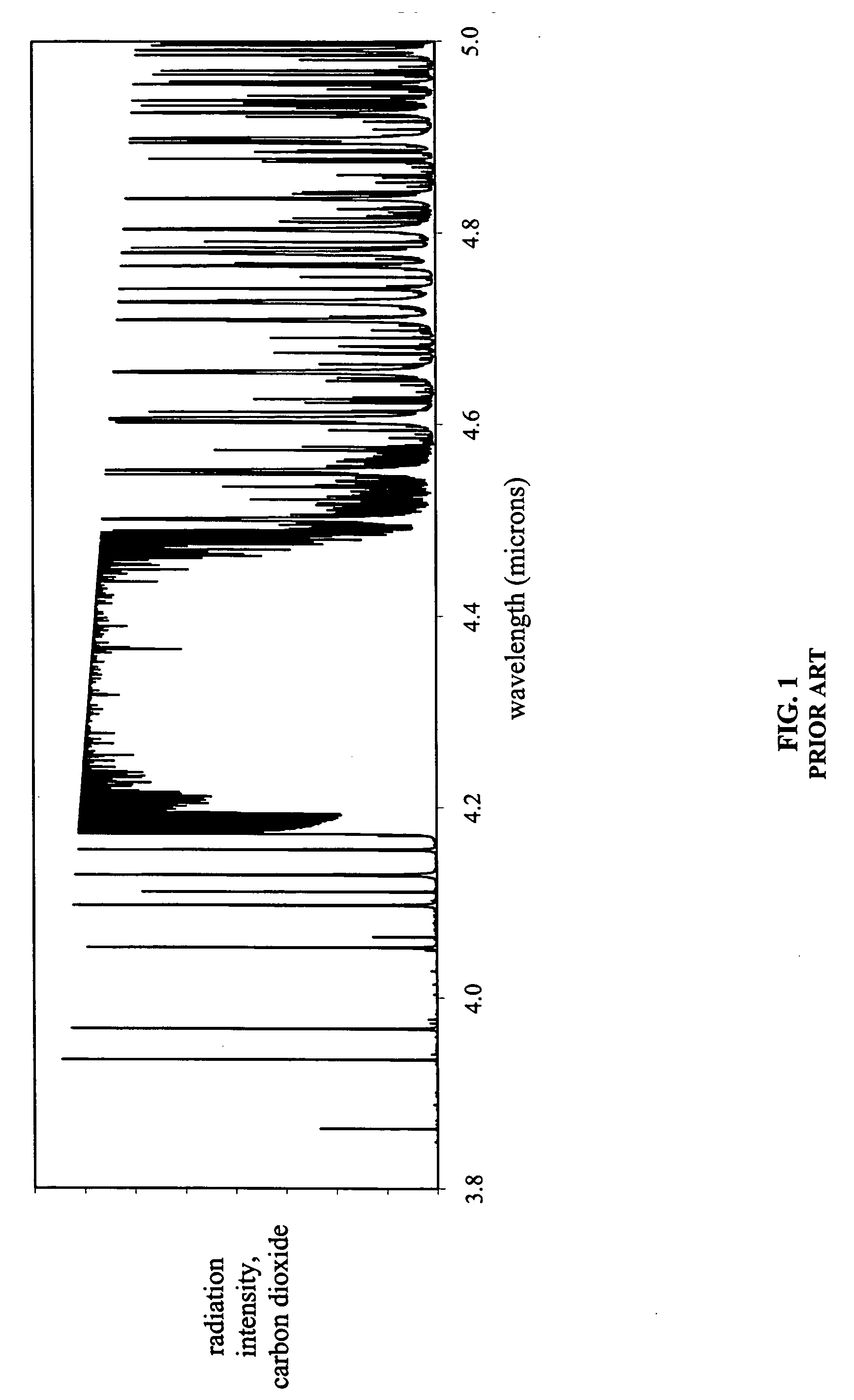
However, regardless of its precise shape, this peak typically is exhibits relatively strong emissions with relatively weak emissions immediately to either side.
However, not all flames generate significant quantities of carbon dioxide.
Some fuels lack carbon altogether, and thus do not produce carbon dioxide when burned.
Since burning these fuels does not produce carbon dioxide, sensing the characteristic infrared emission spectrum of carbon dioxide will not be a reliable approach for detecting such flames.
However, the infrared emission spectra produced by burning carbon-free fuels typically is different from the infrared emission spectra produced by burning carbon-bearing fuels.
However, the emission spectra of carbon-free fuels, which due to their lack of carbon do not generate significant quantities of carbon dioxide, typically do not exhibit the 4.4 micron carbon dioxide peak.
Moreover, the emission spectra of carbon-free fuels may not exhibit any other similarly well-defined peak that might be analyzed in a similar conventional manner.
Given such an emission spectrum, conventional analysis of a single peak may prove difficult.
However, conventional analysis of those portions of the infrared flame spectrum has not provided a reliable indication of the presence of flames, and / or has not reliably excluded false alarm sources.
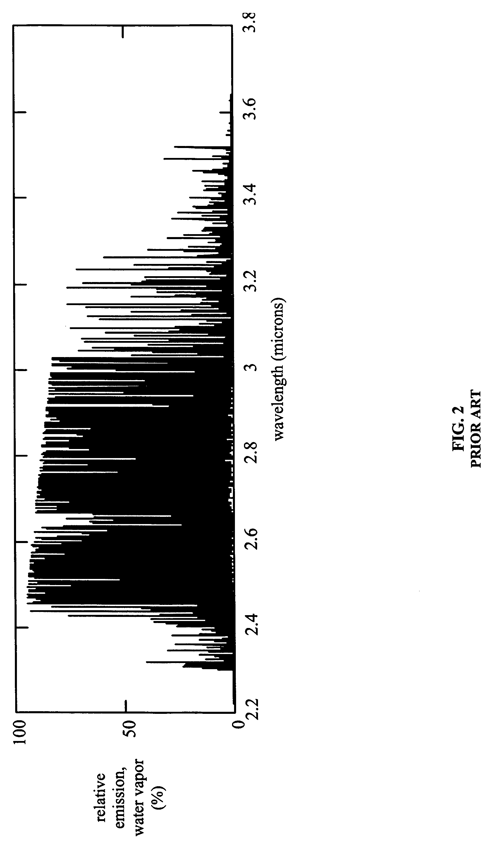
However, with closely spaced peaks as shown in FIGS. 2 and 3, defining areas of low intensity to either side of a particular peak may be difficult.
Even if achieving such a narrow bandwidth is possible, it may be impractical.
Again, assuming a design is available to provide such precision in aligning the band to sense a peak such as those in FIG. 3, it may not be practical to manufacture.
Furthermore, the use of conventional optics changes the apparent wavelength of incident radiation.
Thus, even if a filter or other selector can be made with a suitably small bandwidth and a suitably precise pass band, a conventional approach to flame detection using a water emission band (or a band similarly lacking in readily isolated peaks) still would face significant obstacles to success in detecting actual flames.
Infrared radiation from these sources may be misinterpreted as a flame, thus producing a false alarm condition.
However, simply ignoring or filtering the radiation to exclude false alarms from such non-flame sources may result in actual flames being masked.
Conventionally, however, it may be difficult to determine reliably whether the overall shape of an infrared signal, particularly one that is broadly distributed in terms of wavelength, and / or of relatively low intensity, is representative of a fire or a false alarm source.
However, such an arrangement is not necessarily sufficient to distinguish between an actual fire and a false alarm.
Consequently, such an arrangement may not be sufficient to reliably distinguish flames from false alarms.
However, increasing the number of monitored bands can increase the complexity of a detector.
In summary, using conventional approaches for infrared sensing of flames from carbon-free fuels may pose difficulties with regard to accurate detection of flames, reliability in rejecting false alarms, and complexity.
However, conventional approaches for sensing ultraviolet and / or visible radiation from flames burning carbon-free fuels may pose similar difficulties to those described with regard to the conventional sensing of infrared radiation.
However, for many fuels the ultraviolet emission spectrum is weak and / or spread out.
As noted above, the lack of a strong infrared peak poses difficulties for conventional infrared detectors.
The lack of a well-defined ultraviolet peak presents similar difficulties for ultraviolet detectors.
In addition, as with conventional infrared detectors, false alarms are also a concern with ultraviolet flame detectors.
However, those vapors may absorb ultraviolet radiation that is relied upon by some conventional flame detectors.
Consequently, the vapors themselves may interfere with conventional flame detection, and / or false alarm exclusion.
However, many carbon-free fuels emit only minimal amounts of visible radiation.
In particular, molecular hydrogen is notoriously difficult to identify in visible light.
However, such combinations conventionally may suffer from limitations similar to those of their individual spectra.
For example, a conventional UV-IR flame detector may be unable to detect ultraviolet light in the presence of hydrocarbons; if ultraviolet radiation is relied upon by that detector in order to identify a fire and / or exclude false alarm sources, the lack of that ultraviolet radiation at the detector due to the presence of hydrocarbons may interfere with the detector's operation.
Thus, conventional approaches for using visible light to reliably detect carbon-free flames while avoiding false alarms also may be problematical.
Even for burning fuels that include carbon, and that emit hot carbon dioxide, conventional reliance on the carbon dioxide peak at 4.4 microns may pose difficulties in at least some circumstances.
One such potential contaminant is cool carbon dioxide.
This may reduce the sensitivity of conventional carbon dioxide spectrum flame detectors.
However, the very act of suppressing that fire may effectively “blind” conventional carbon dioxide spectrum flame detectors in the vicinity.
In such circumstances, it might be difficult to determine whether the fire is extinguished or is still burning without clearing the area of the carbon dioxide fire suppressant.
Moreover, conventional carbon dioxide spectrum infrared flame detectors may have at best limited facility for discriminating between distant fires and fires within the area they are tasked to protect.
With conventional carbon dioxide spectrum infrared flame detectors it may be difficult to distinguish between a flame that is present in a monitored area, and thus represents a potential hazard, and a flame that is far from the monitored area.
For example, petroleum drilling and processing facilities often have large stack fires or “flares” that burn off hydrocarbon gas.
Stack flares typically represent known phenomena, and generally are not considered a legitimate alarm source.
However, stack flares often are visible for miles.
It may be difficult to distinguish with a conventional carbon dioxide spectrum infrared flame detector between a distant stack flare and a potentially hazardous flame nearby.

Method used


Image

  • Hydrogen fire detection system & method
  • Hydrogen fire detection system & method
  • Hydrogen fire detection system & method

Examples


Embodiment Construction

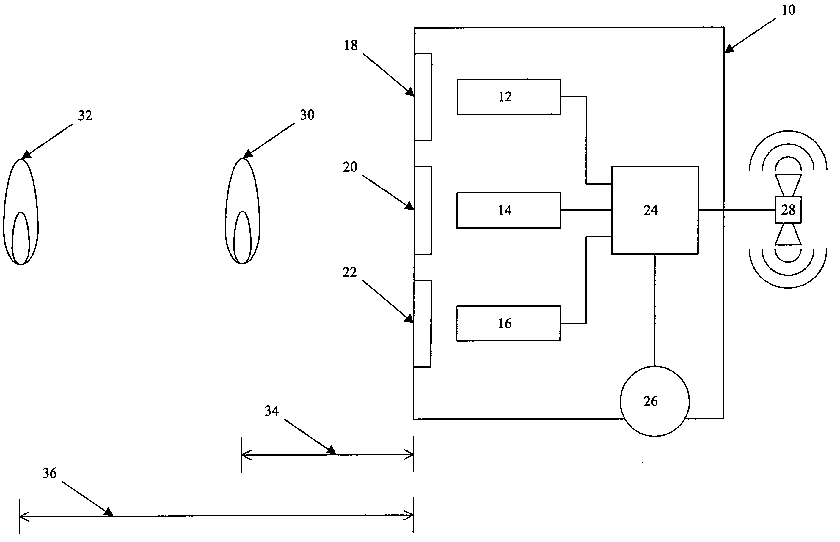
[0081] Referring to FIG. 4, an exemplary embodiment of an apparatus 10 for detecting flames in accordance with the principles of the claimed invention includes a first sensor 12, a second sensor 14, and a third sensor 16.

[0082] As previously noted, hot water, such as in the form of vapor, emits a characteristic spectrum of infrared radiation. Each of the first, second, and third sensors 12, 14, and 16 is sensitive to a region of an emission band in the characteristic spectrum of infrared radiation associated with hot water.

[0083] For exemplary purposes, the water emission band referred to herein is considered to be the range of infrared wavelengths extending from approximately 2.3 microns to approximately 3.5 microns, inclusive. This band is illustrated in FIG. 2, and a portion thereof is illustrated in FIG. 3.

[0084] However, this definition is exemplary only. Other ranges of wavelengths may be equally suitable for consideration as an infrared emission band for water. For example...


PUM


Abstract

To detect flames burning carbon-free hydrogen-bearing fuels, first, second, and third sensors sense first, second and third regions of an infrared water emission band, and generate first, second, and third signals. A processor generates an alarm when the sensors indicate flame. The first region low cut-off wavelength may be lower than the second region low cut-off wavelength. The third region high cut-off wavelength may be higher than the second region high cut-off wavelength. The combined regions may include nearly the entire water emission band. The processor may discriminate distances to flames using the sensor signals. A fourth sensor may sense moisture concentration, and the processor may discriminate distances based thereon. The regions may be defined such that for a fire, all three regions receive substantial energy, with second region to first region energy ratio less than 1:1 and a second region to third region energy ratio less than 1:1.

Description

[0001] This application claims the benefit of U.S. Provisional Application Ser. No. 60 / 550,501, filed Mar. 5, 2004, and entitled HYDROGEN FIRE DETECTION SYSTEM AND METHOD. This application also incorporates in its entirety U.S. Pat. No. 5,995,008, issued Nov. 30, 1999, and entitled FIRE DETECTION METHOD AND APPARATUS USING OVERLAPPING SPECTRAL BANDS.BACKGROUND OF THE INVENTION [0002] The invention relates to an apparatus and method for detecting flames. More particularly, the invention relates to an apparatus and method for detecting flames by measuring at least three regions of infrared radiation emitted by water vapor that is produced as a product of combustion. [0003] Flames emit electromagnetic radiation across a range of wavelengths. The precise wavelengths may vary from flame to flame, depending on variables such as the fuel being burned. Conventional optical flame detectors operate by sensing one or more wavelengths of electromagnetic radiation. [0004] Many combustible materi...

Claims


Application Information

Patent Timeline
Patent Type & Authority Applications(United States)
IPC IPC(8): G01J5/00G08B17/12
CPCG01J5/0014
Inventor KING, JOHN D.
Owner DETECTOR ELECTRONICS CORP
Learn More