Element arrangement board and element arrangement method

a technology of element arrangement and element arrangement, which is applied in the direction of metal working apparatus, transportation and packaging, coatings, etc., can solve the problems of long time required before the elements b>12/b>, and the inability of image display apparatus such as lcd or pdp to allow element isolation with regard to the pitch of elements or pixels, so as to achieve efficient movement toward the recess and further efficient

Inactive Publication Date: 2005-09-08
SONY CORP
View PDF6 Cites 37 Cited by
  • Summary
  • Abstract
  • Description
  • Claims
  • Application Information

AI Technical Summary

Benefits of technology

[0015] Since the tapered faces are formed as faces inclined downwardly toward the recesses in the element arrangement board, an element placed on any of the tapered faces is acted upon by force toward the recess and consequently can be moved toward the recess efficiently. Further, if the element is placed on a flat arrangement face, then it repeats random movement similar to Brownian motion when ultrasonic vibrations are applied. However, since a downward slope toward the recess is provided on the tapered face, the probability that the element placed on the tapered face may move toward the fitting hole can be enhanced. Consequently, the element can be moved further efficiently toward the fitting hole. Accordingly, since the time before the element reaches the recess can be shortened, even if the number of elements to be supplied to the arrangement face is decreased when compared with that in the related art techniques, the elements can be fitted into the recesses and arranged with certainty.
[0016] Where the area of the tapered faces is greater than ten times the area of the recesses, the elements supplied to the arrangement face can be moved to locations proximate to the recesses efficiently. Further, where the recesses and the tapered faces are formed periodically on the arrangement face of the element arrangement board body, the element arrangement board can be used directly in an image display apparatus or a like apparatus. Each of the recesses may be formed substantially at the center of one of the tapered faces.

Problems solved by technology

A conventional image display apparatus such as an LCD or a PDP does not allow element isolation with regard to the pitch of elements or pixels.
Therefore, the technique described has a problem in that the time required before the elements 12 are fitted into all of the holes 11 is long and the throughput is low.
Therefore, the technique described above has a problem in that the required number of parts is great and a high production cost is required.

Method used


Image

  • Element arrangement board and element arrangement method
  • Element arrangement board and element arrangement method
  • Element arrangement board and element arrangement method

Examples


Embodiment Construction

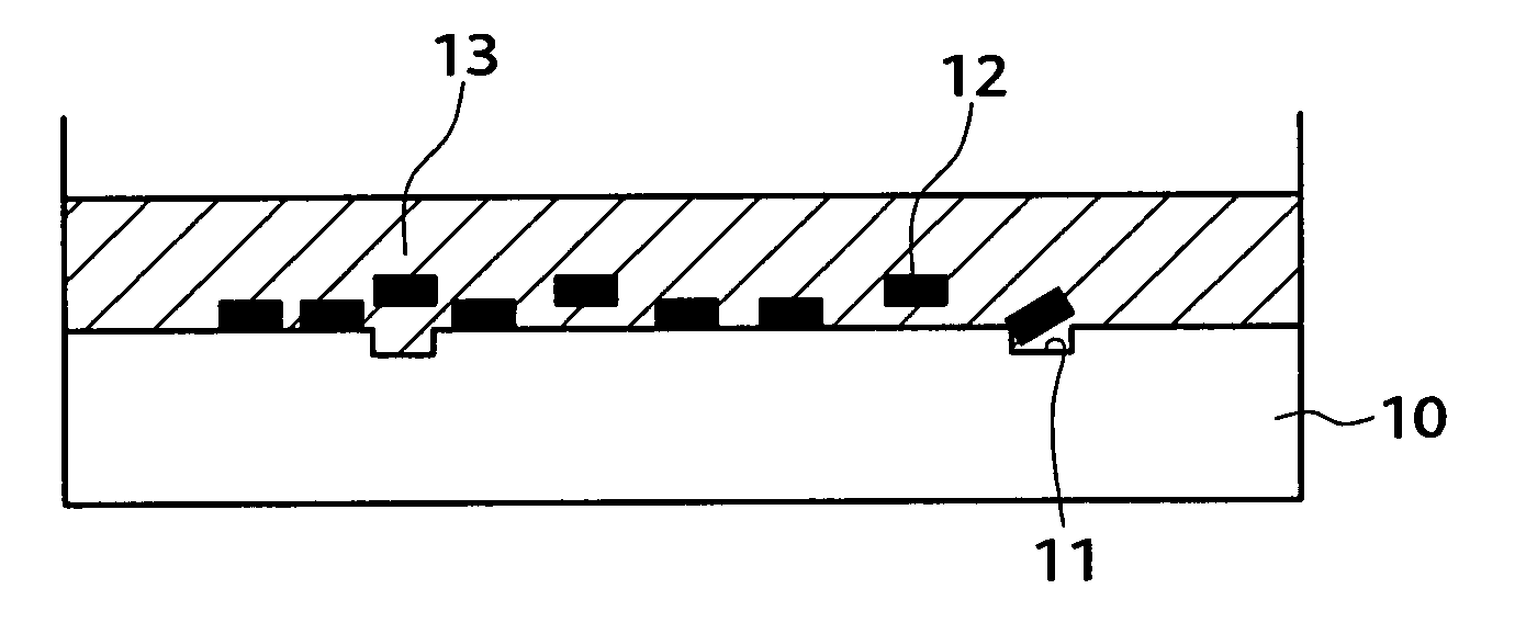
[0030] The present invention relates to an element arrangement board and an element arrangement method for arranging a plurality of elements at predetermined positions. More particularly, the present invention relates to an element arrangement board and an element arrangement method for arranging a plurality of elements in a self-aligning fashion using motion of the elements in fluid.

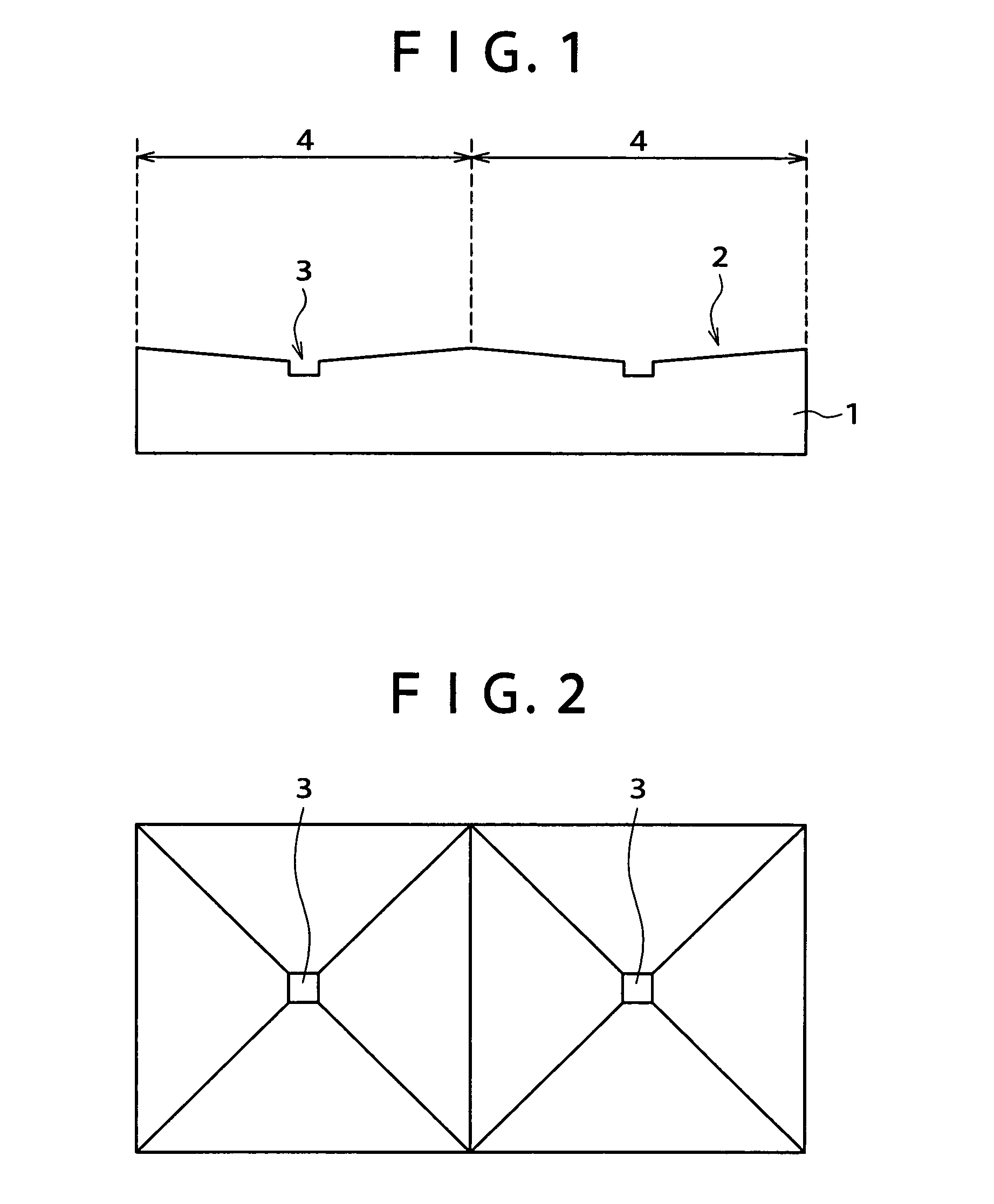
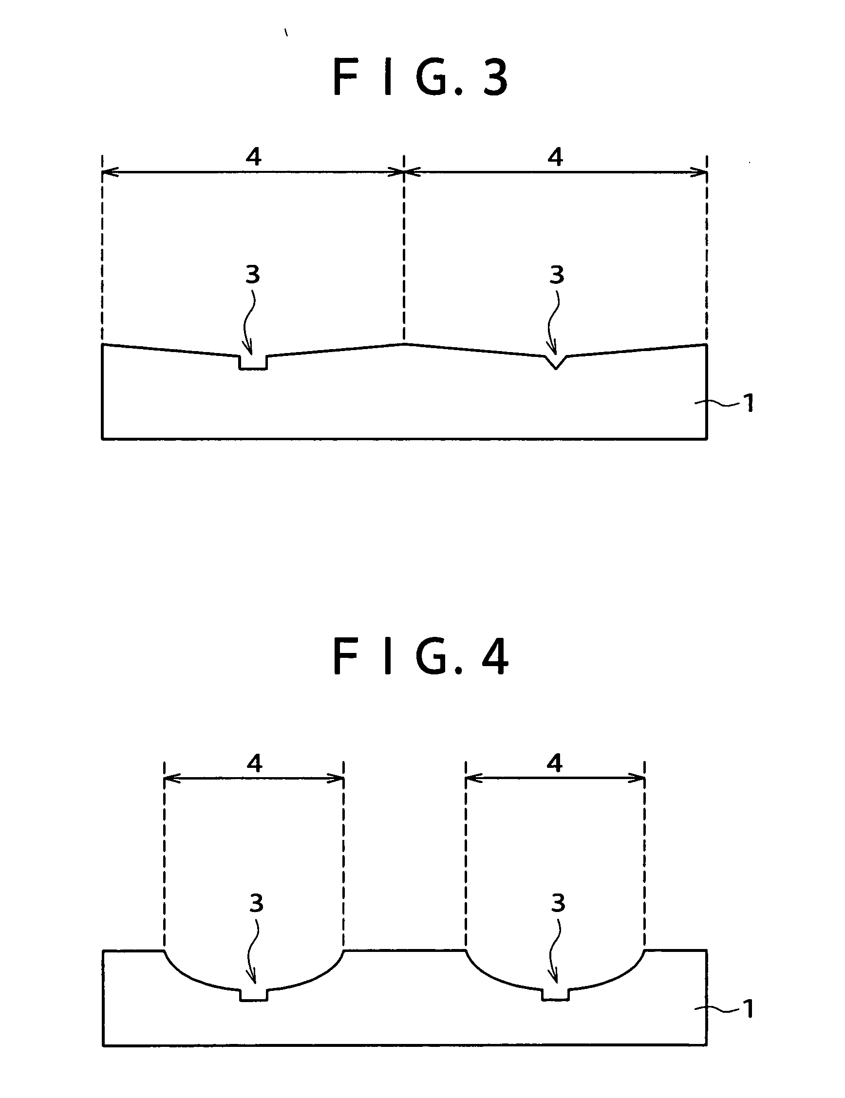
[0031] Referring to FIGS. 1 and 2, a structure of an element arrangement board to which the present invention is applied is shown. According to the element arrangement board and the element arrangement method of the present invention, an arrangement face 2 for arranging elements thereon is formed on one of the opposite faces of an element arrangement board 1 which is a plate-like member. The arrangement face 2 has fitting holes 3 formed thereon for fixedly receiving elements therein. An inclined tapered face 4 is formed in a region of the arrangement face 2 indicated by a double-sided arrow mark around...


PUM

PropertyMeasurementUnit
specific gravityaaaaaaaaaa
sizeaaaaaaaaaa
sizeaaaaaaaaaa

Abstract

An element arrangement board and method are provided. Where the element size is comparatively small with respect to the distance in element arrangement and the density of arranged elements is low, the elements can also be arranged with certainty and efficiently in a short period of time. The element arrangement board has an arrangement face on which fitting holes for receiving elements are formed and tapered faces are formed around the fitting holes and inclined downwardly toward the fitting holes. Elements to be arranged are mixed in fluid. The fluid is supplied to the arrangement face of the element arrangement board. The elements are acted upon by force toward the fitting holes on the tapered faces so that they are fitted in a self-aligned fashion into the fitting holes and arranged on the element arrangement board.

Description

CROSS REFERENCE TO RELATED APPLICATION [0001] This application claims priority to Japanese Patent Document No. 2004-012828, filed on Jan. 21, 2004 with the Japanese Patent Office, which disclosure in its entirety is hereby incorporated by reference. BACKGROUND OF THE INVENTION [0002] The present invention relates to an element arrangement board and an element arrangement method for arranging a plurality of elements at predetermined positions. More particularly, the present invention relates to an element arrangement board and an element arrangement method for arranging a plurality of elements in a self-aligning fashion using motion of the elements in fluid. [0003] Conventionally, to arrange and assemble elements in a matrix to an image display apparatus, the elements are formed on a board as in a liquid crystal display (LCD) panel or a plasma display panel (PDP). Alternatively, independent LED packages are disposed on a board as in a light emitting diode (LED) display unit. A conven...

Claims


Application Information

Patent Timeline
Patent Type & Authority Applications(United States)
IPC IPC(8): H01L23/12B05D5/00B32B3/00H01L21/68H01L21/98
CPCH01L24/95H01L25/50H01L2224/95085H01L2224/95122H01L2924/01082Y10T29/49998H01L2924/01006H01L2924/01033H01L2924/12041Y10T428/24612H01L2924/01005H01L2924/15787H01L2924/181H01L2924/00
Inventor WATANABE, TOSHIHIKO
Owner SONY CORP
Why Eureka
Try Eureka