Dry cleaner and drying machine

a technology of drying machine and dryer, which is applied in the field of drying machine, can solve the problems of environmental problems, remarkably difficult installation operation such as piping work, and poor generation efficiency

Inactive Publication Date: 2005-09-15
SANYO ELECTRIC CO LTD
View PDF18 Cites 25 Cited by
  • Summary
  • Abstract
  • Description
  • Claims
  • Application Information

AI Technical Summary

Benefits of technology

[0040] The circulation of the cooling water into the water-cooling heat exchanger is stopped from the start of the drying step until the temperature of the air passed thro...

Problems solved by technology

Therefore, an installation operation such as a piping work has been remarkably difficult in an environment where it is difficult to install the boiler.
However, in a conventional dry cleaner using a petroleum boiler, there is fear that the environmental problem is caused by consumption of petroleum fuel.
However, in the drying machine in which the electric heater is used, a heat generation efficiency (ratio of a generated heat amount with respect to projected power) is ...

Method used


Image

  • Dry cleaner and drying machine
  • Dry cleaner and drying machine
  • Dry cleaner and drying machine

Examples


embodiment 1

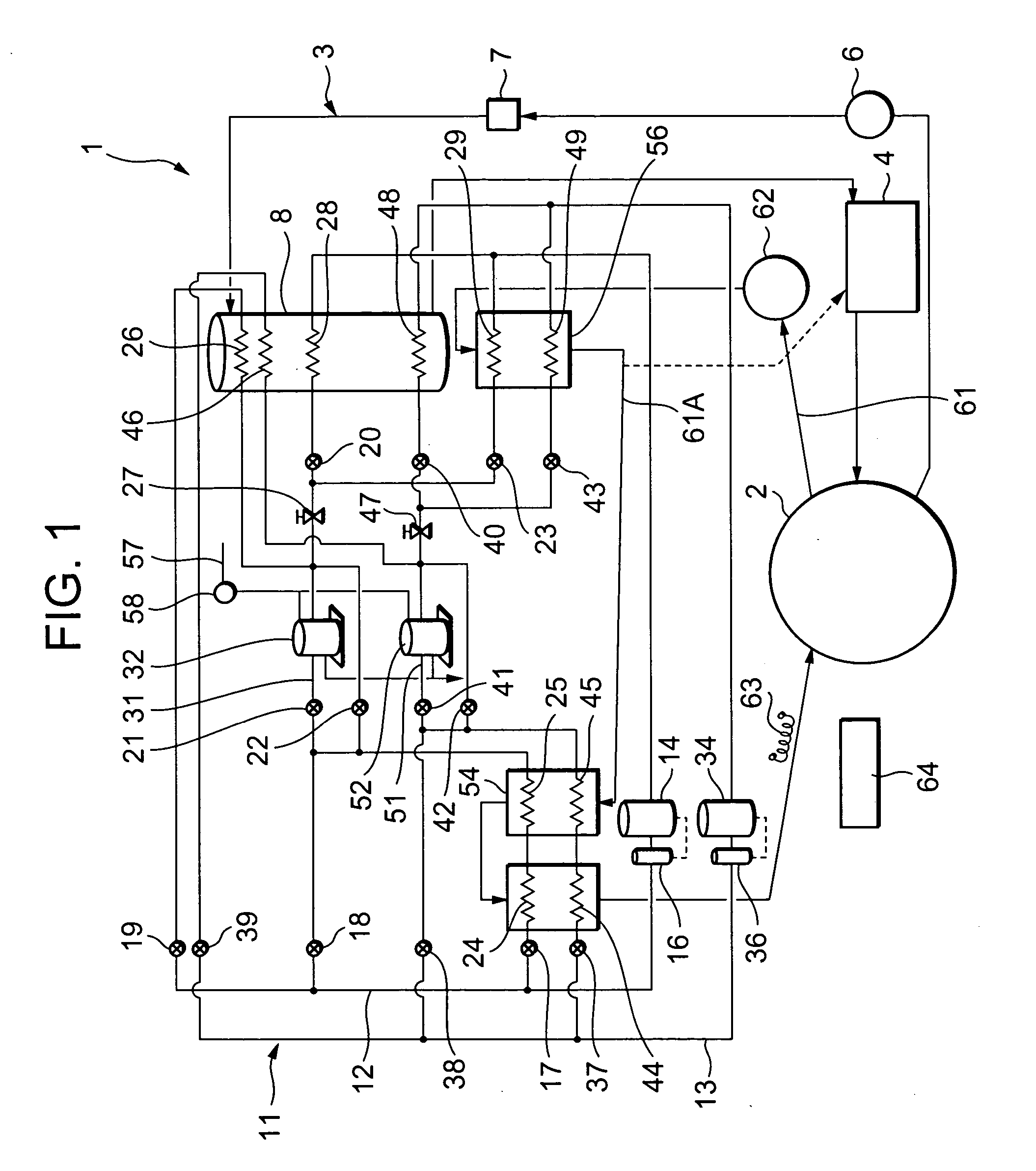
[0062]FIG. 1 shows a constitution diagram of a dry cleaner 1 according to one embodiment of the present invention. FIG. 8 shows a rear perspective view of the dry cleaner 1, and FIG. 9 shows a perspective view of a heat pump device 11 of the dry cleaner 1 in FIG. 8. In the respective figures, reference numeral 2 denotes a cylindrical drum including a large number of through holes formed in a peripheral wall, clothing is washed by a washing liquid in this drum 2, and subsequently drying is also performed. This drum 2 is rotated by a drum motor (not shown), for example, at a speed of 30 to 50 rpm.

[0063] Moreover, reference numeral 3 denotes a washing liquid circulation channel for circulating the washing liquid in the drum 2, and the washing liquid circulation channel 3 is connected to a washing liquid tank 4, a washing liquid pump 6, a filter 7, a washing liquid temperature control tank 8 and the like. When the washing liquid pump 6 is operated, the washing liquid is supplied to the...

embodiment 2

[0106] Next, another embodiment of the present invention will be described in detail with reference to FIGS. 10 to 19.

[0107] In this case, there is provided a drying machine capable of reducing a drying time of a matter to be dried.

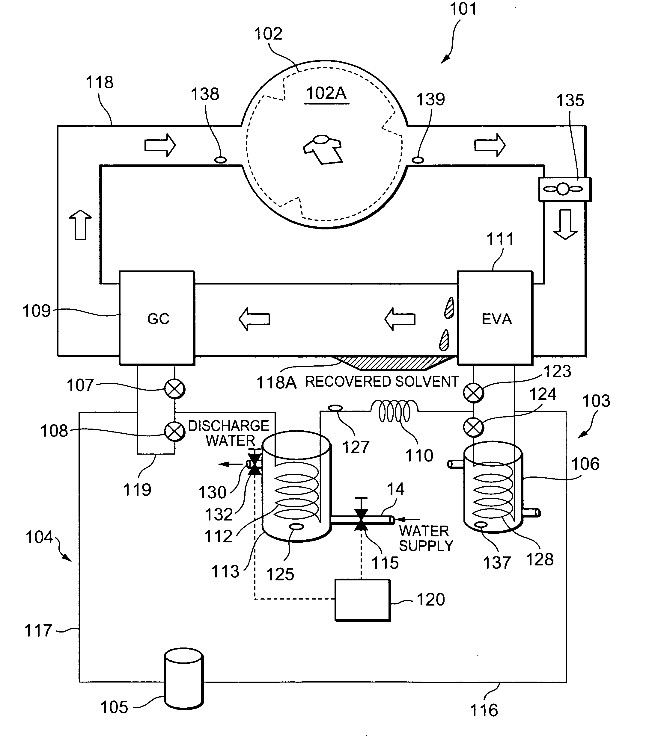
[0108]FIG. 10 shows a schematic constitution diagram of a dry cleaner 101 using, for example, a petroleum-based solvent as a washing liquid in one embodiment of a drying machine to which a heat pump device 103 of the present invention is applied in this case. In this figure, reference numeral 102 denotes a cylindrical drum including a large number of through holes formed in a peripheral wall. Clothing or the like is stored as a matter to be washed (matter to be dried in a recovering•drying step) in a storage chamber 102A in the drum 102. In the storage chamber 102A, steps of washing, dewatering, and drying the clothing by a washing liquid are executed. That is, the dry cleaner 101 performs the washing and the subsequent drying in the storage chamber 102...


PUM


Abstract

An object is to provide a dry cleaner in which an installing operation is facilitated and in which environments are taken into consideration, and the dry cleaner rotates a drum containing clothing and successively executes a washing step using a washing liquid, a dewatering step, and a drying step. Heating and cooling units for executing the respective steps comprise a heat pump device, the washing liquid is heated by the heat pump device using carbon dioxide as a refrigerant of a refrigerant circuit constituting the heat pump device, the washing liquid is cooled by the heat pump device, air supplied to the drum in the drying step is heated by the heat pump device, and the air discharged from the drum in the drying step is cooled by the heat pump device.

Description

BACKGROUND OF THE INVENTION [0001] The present invention relates to a dry cleaner which executes steps of washing•dewatering and drying clothing in a drum using a solvent such as silicon as a washing liquid. [0002] Moreover, the present invention relates to a drying machine comprising a water-cooling type heat exchanger for taking heat of a refrigerant which enters expansion means. [0003] In a dry cleaner, a petroleum-based solvent has heretofore been supplied into a drum. After washing clothing, the solvent in the drum is discharged to rotate the drum at a high speed, and the clothing is dewatered. Moreover, to dry the clothing, dry air (high-temperature air) is circulated in the drum, the solvent is evaporated from the clothing, and drying is performed (see, e.g., Japanese Patent Application Laid-Open No. 8-173688). [0004] However, steam generated by a petroleum boiler or the like has heretofore been used as a heating source of air for drying, and cooling water has been used as a ...

Claims


Application Information

Patent Timeline
IPC IPC(8): D06F43/00D06F43/08
CPCD06F43/086D06F43/007
Inventor TADANO, MASAYAMASUDA, TATSUYAMUKAIYAMA, HIROSHINISHINO, MASAFUMIASADA, NOBUHIRONAGANAWA, MITSURU
Owner SANYO ELECTRIC CO LTD
Why Eureka
Try Eureka