Method for manufacturing magnetic sensor, magnet array used in the method, and method for manufacturing the magnet array

a technology of magnetic sensor and magnet array, which is applied in the direction of galvano-magnetic devices, instruments, solid-state devices, etc., can solve the problems of difficult mass production of small-sized biaxial magnetic sensors using synthetic spin valve films, and difficult generation of such magnetic fields

Inactive Publication Date: 2005-09-15
YAMAHA CORP
View PDF7 Cites 18 Cited by
  • Summary
  • Abstract
  • Description
  • Claims
  • Application Information

AI Technical Summary

Benefits of technology

[0009] An object of the present invention is to provide a method for manufacturing a magnetic sensor which enables mass production of small-sized bia

Problems solved by technology

However, generation of such magnetic fields is very difficult.
As a result, a small-sized biaxial

Method used


Image

  • Method for manufacturing magnetic sensor, magnet array used in the method, and method for manufacturing the magnet array
  • Method for manufacturing magnetic sensor, magnet array used in the method, and method for manufacturing the magnet array
  • Method for manufacturing magnetic sensor, magnet array used in the method, and method for manufacturing the magnet array

Examples


Embodiment Construction

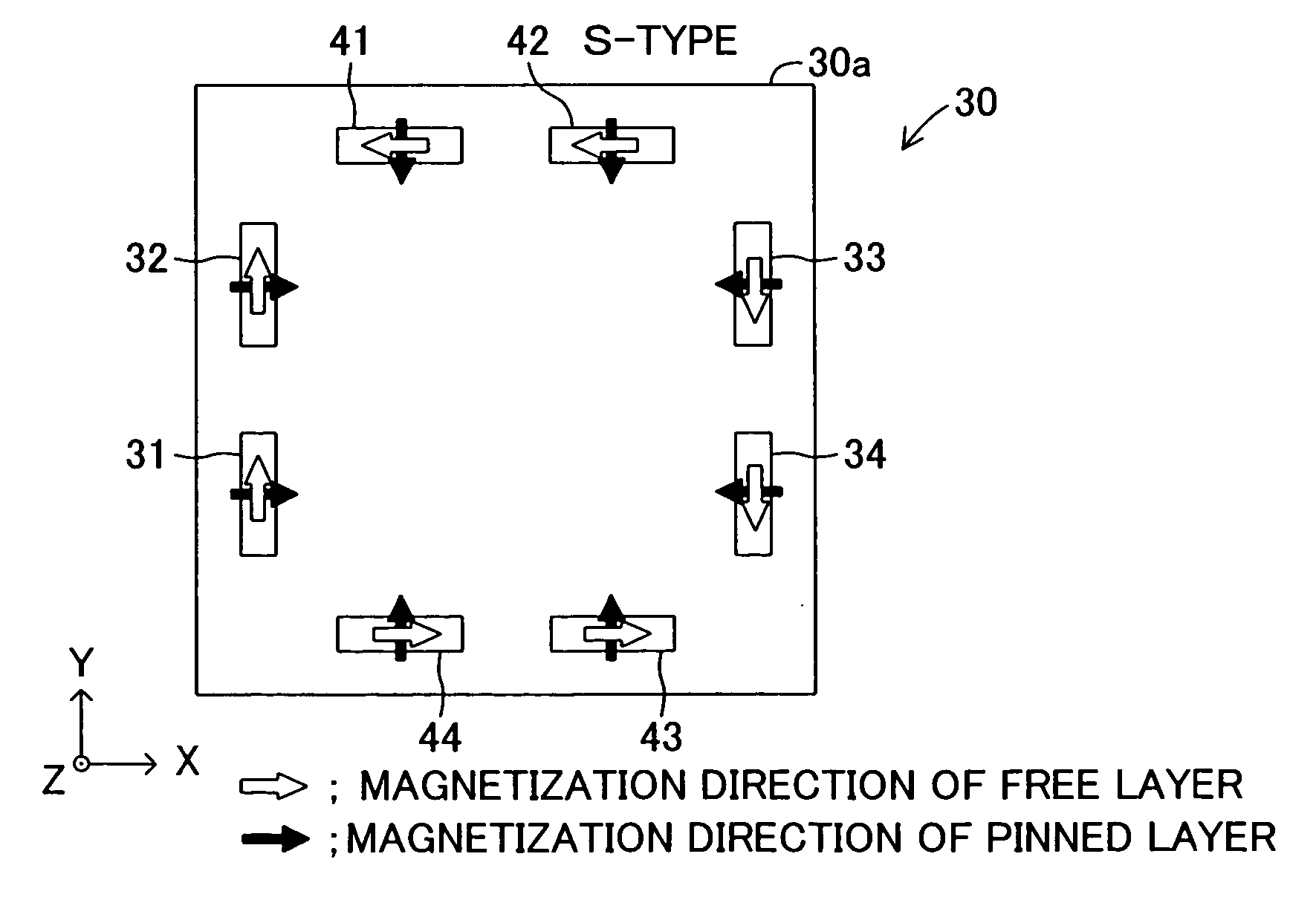
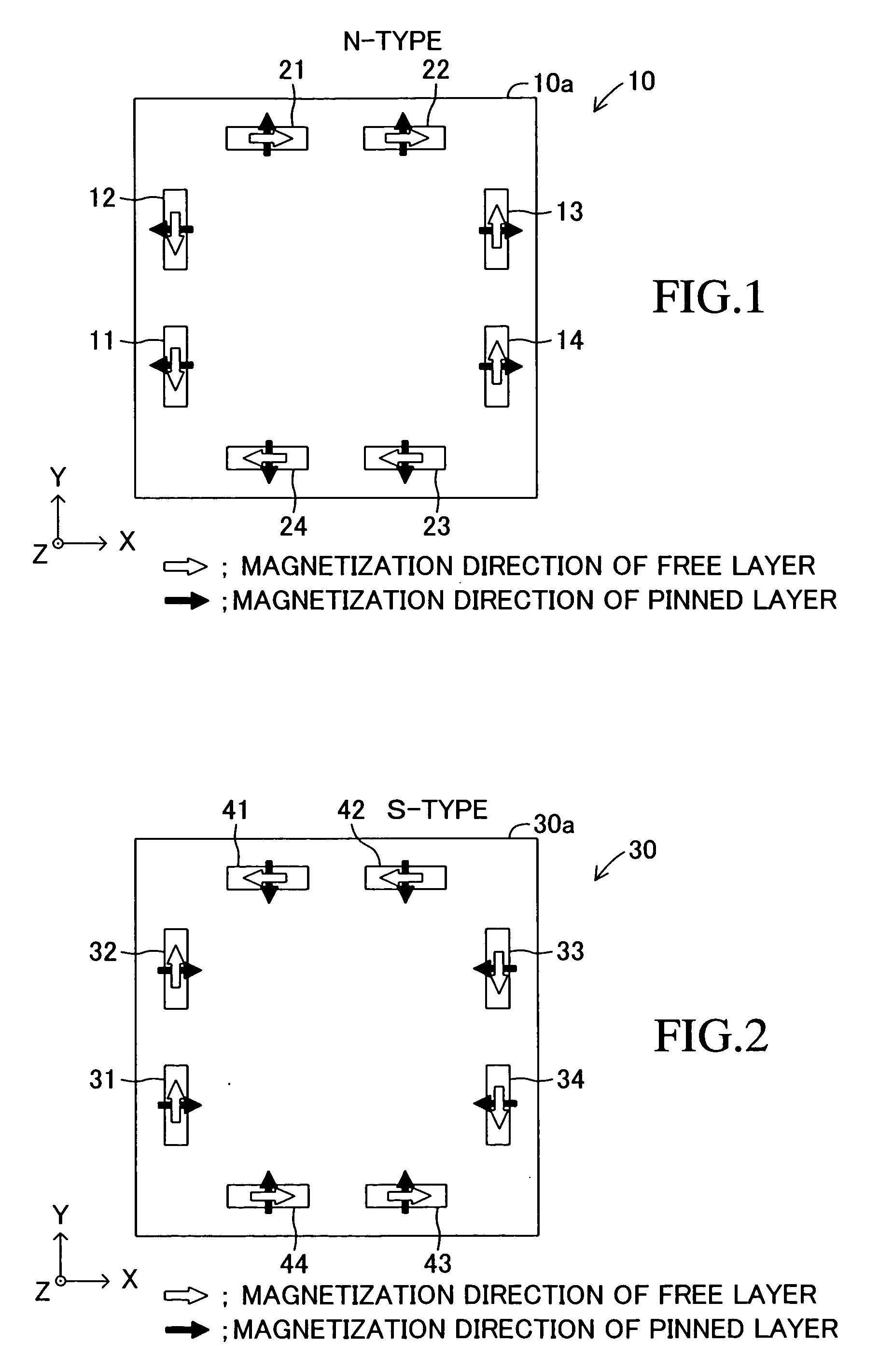
[0093] Embodiments of the present invention will next be described in detail with reference to the drawings. An embodiment of a magnetic sensor according to the present invention will be first described. The magnetic sensor is classified into an N-type magnetic sensor 10 shown in FIG. 1 and an S-type magnetic sensor 30 shown in FIG. 2. The N-type and S-type magnetic sensors 10 and 30 are manufactured by manufacturing methods to be described later.

[0094] The N-type magnetic sensor 10 and the S-type magnetic sensor 30 assume substantially the same shape and configuration except for the fixed magnetization direction of a pinned layer as represented by the black solid arrow of FIGS. 1 and 2 and the magnetization direction of a free layer in an initial state (a state in which an external magnetic field is absent) as represented by the inline arrow of FIGS. 1 and 2. Therefore, the N-type magnetic sensor 10 will be mainly discussed below.

[0095] As shown in FIG. 1, the magnetic sensor 10 ...


PUM

PropertyMeasurementUnit
Shapeaaaaaaaaaa

Abstract

A magnetic sensor includes eight SAF-type GMR elements. Four of the GMR elements detect a magnetic field in the direction of the X-axis and are bridge-connected to thereby constitute an X-axis magnetic sensor. The other four GMR elements detect a magnetic field in the direction of the Y-axis and are bridge-connected to thereby constitute a Y-axis magnetic sensor. The magnetization of a pinned layer of each of the GMR elements is pinned in a fixed direction by means of a magnetic field that a permanent bar magnet inserted into a square portion of a yoke of a magnet array generates in the vicinity of a rectangular portion of the yoke. A magnetic field generated in the vicinity of a certain rectangular portion of the yoke differs in direction by 90 degrees from a magnetic field generated in the vicinity of a rectangular portion adjacent to the former rectangular portion.

Description

BACKGROUND OF THE INVENTION [0001] 1. Field of the Invention [0002] The present invention relates to a method for manufacturing a magnetic sensor using a magnetoresistance element (so-called synthetic spin valve film) having a multifilm laminated fixed layer, to a magnet array suited for use in the method, and to a method for manufacturing the magnet array. [0003] 2. Description of the Related Art [0004] A conventionally known giant magnetoresistance element (hereinafter referred to as a “GMR element”) includes a fixed layer that includes a pinned layer, and a pinning layer for pinning the magnetization of the pinned layer in a fixed direction; a free layer whose magnetization direction varies in accordance with an external magnetic field; and a spacer layer disposed between the pinned layer and the free layer and made of a nonmagnetic electric conductor. The resistance of the GMR element varies in accordance with the angle between the magnetization direction of the pinned layer and...

Claims


Application Information

Patent Timeline
IPC IPC(8): G01R33/09H01L43/02H01L43/00H01L43/08H01L43/12
CPCB82Y25/00Y10T29/49021Y10T29/49002G01R33/093H10N50/10
Inventor OOHASHI, TOSHIYUKIAISO, KOKICHI
Owner YAMAHA CORP
Why Eureka
Try Eureka