Device for generating a laser light beam

a laser light and laser light technology, applied in the direction of lasers, laser construction details, instruments, etc., can solve the problems of high labor intensity, difficult for users to individually compose laser light beams comprising several laser lines of individual laser light sources, and inability to train personnel, etc., to achieve high flexibility

Inactive Publication Date: 2005-09-15
LEICA MICROSYSTEMS CMS GMBH
View PDF4 Cites 19 Cited by
  • Summary
  • Abstract
  • Description
  • Claims
  • Application Information

AI Technical Summary

Benefits of technology

[0009] According to the invention, it was recognized that there is a growing tendency towards modular device units which can be employed by users in a simple manner without entailing a lot of retooling or maintenance work. In this context, it was also recognized that special importance is now ascribed to high flexibility and adaptability to the special wishes and requirements of the user. Finally, it was recognized that such flexibility can be attained in that the sources of laser light—either individually or combined in groups—are set up in modular form, whereby the individual modules have mechanical and / or electrical and / or optical interfaces that are defined towards the outside. With such a modular set-up, a user of a confocal microscope, for example, only needs to select those laser modules that match her / his illumination requirements and she / he can then connect them to the microscope via the interfaces that are defined towards the outside within the shortest of time and without special knowledge.

Problems solved by technology

The prior-art devices are problematic because the sources of laser light employed often differ from each other in terms of their mode of operation and they usually come from different manufacturers.
Moreover, the sources of laser light often have different physical dimensions, in addition to which they have different electrical specifications, which makes it extremely difficult for the user to individually compose a laser light beam comprising several laser lines of individual sources of laser light.
Consequently, adding a new source of laser light to an existing system or even merely replacing a single source of laser light entails a great deal of effort and usually can only be done by trained personnel.
It is likewise problematic that, when a source of laser light is replaced, it is generally necessary to replace not only the laser light source itself, but also mechanical parts, optical filters, electrical interfaces, power packs, etc.
Particularly in conjunction with the illumination configuration found in confocal microscopy, in extreme cases, it is even unavoidable that the confocal microscope or at least parts of it will have to be sent to the manufacturer.
In actual practice, this often leads to certain bottlenecks in the utilization of the microscopes, particularly when several experiments are supposed to be carried out at the same time which, due to the concrete requirements made in terms of the illumination, need the same confocal microscope.
The retooling of the microscope that is then necessary entails a considerable expenditure of time and effort on the part of the user.

Method used


Image

  • Device for generating a laser light beam
  • Device for generating a laser light beam
  • Device for generating a laser light beam

Examples


Embodiment Construction

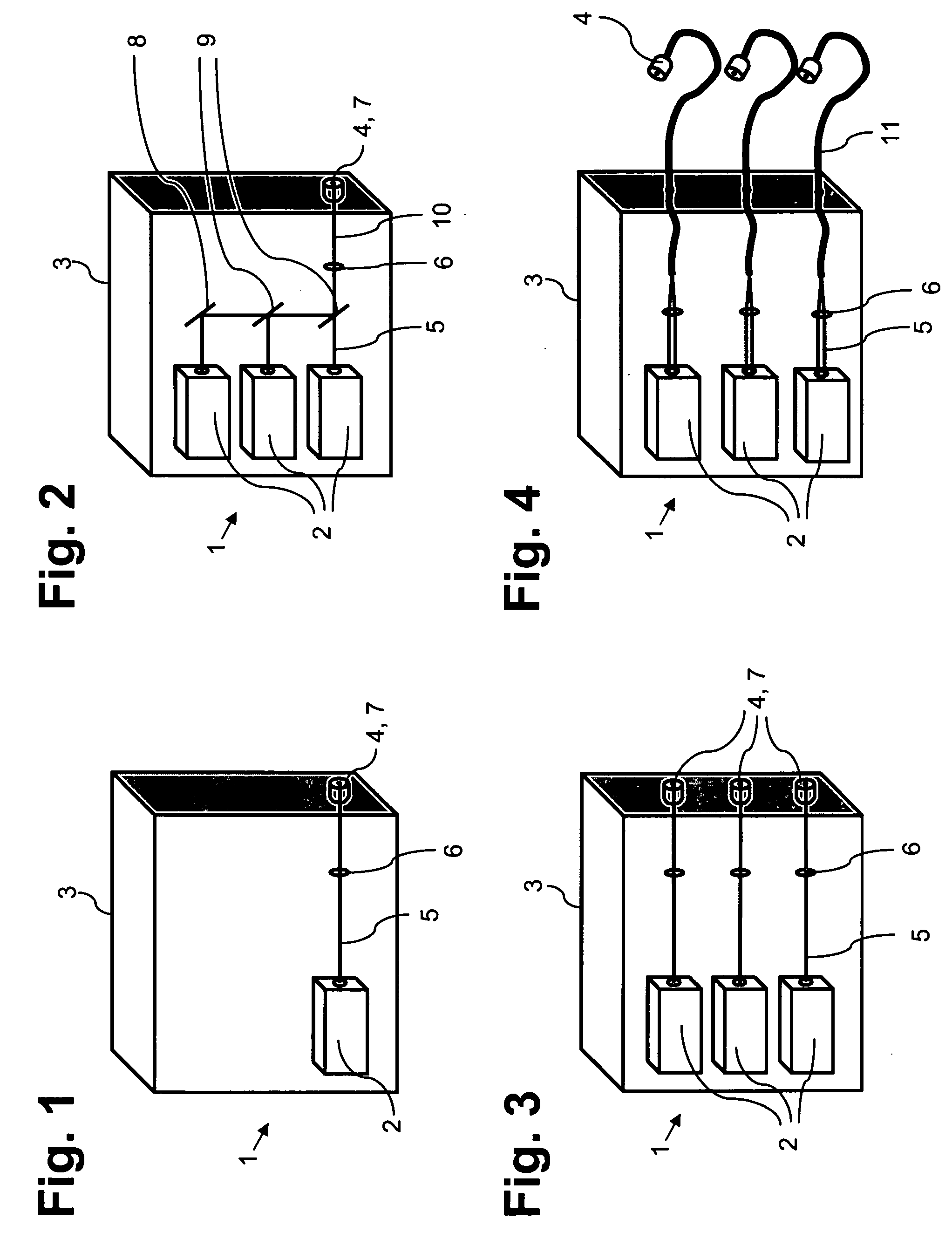
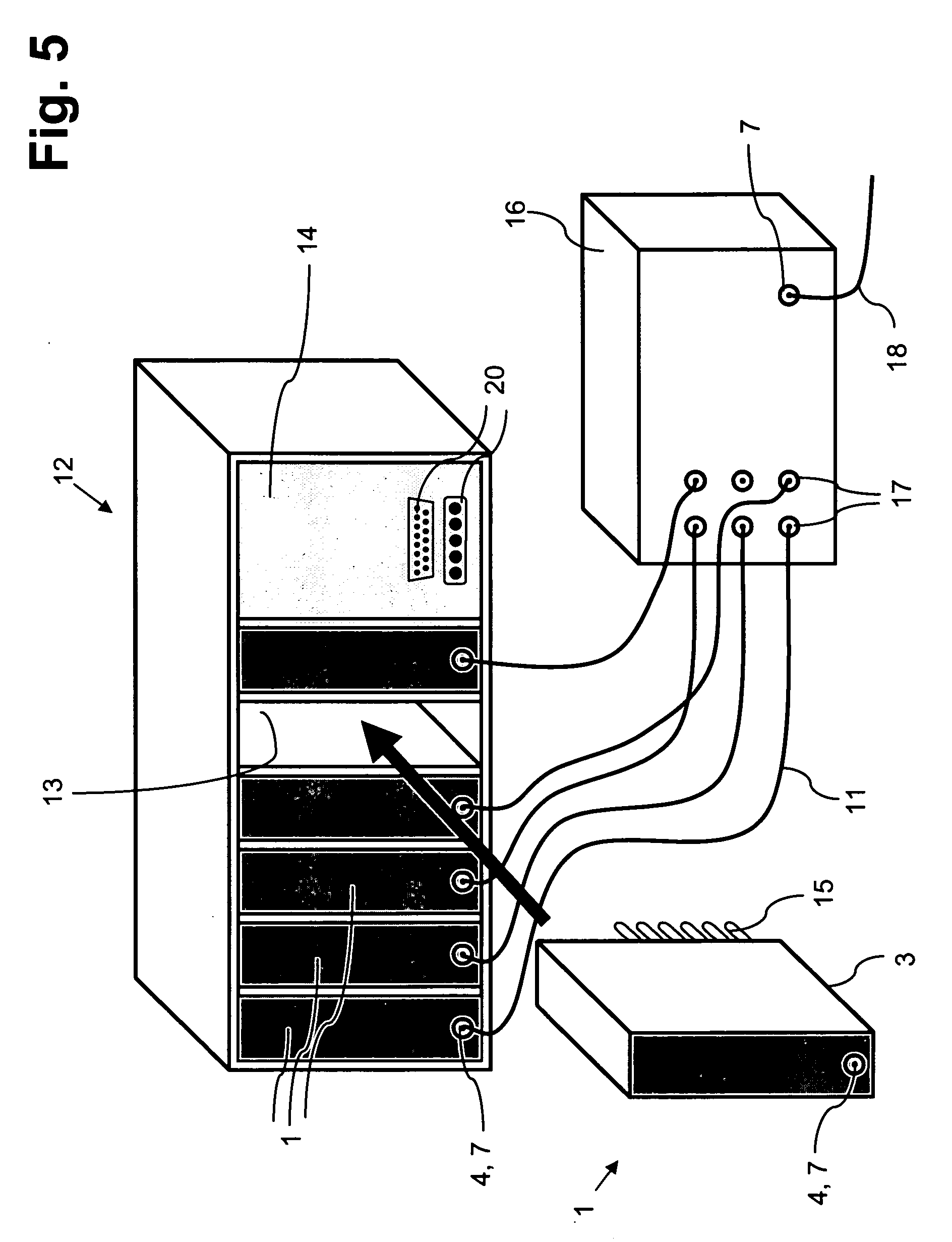
[0017] In a preferred embodiment, there is a docking station with slots into which the individual modules are inserted or slid, whereby the modules can be arranged next to each other and / or above each other inside the docking station. For special applications, the docking station could also be configured with just one slot that accommodates one single module.

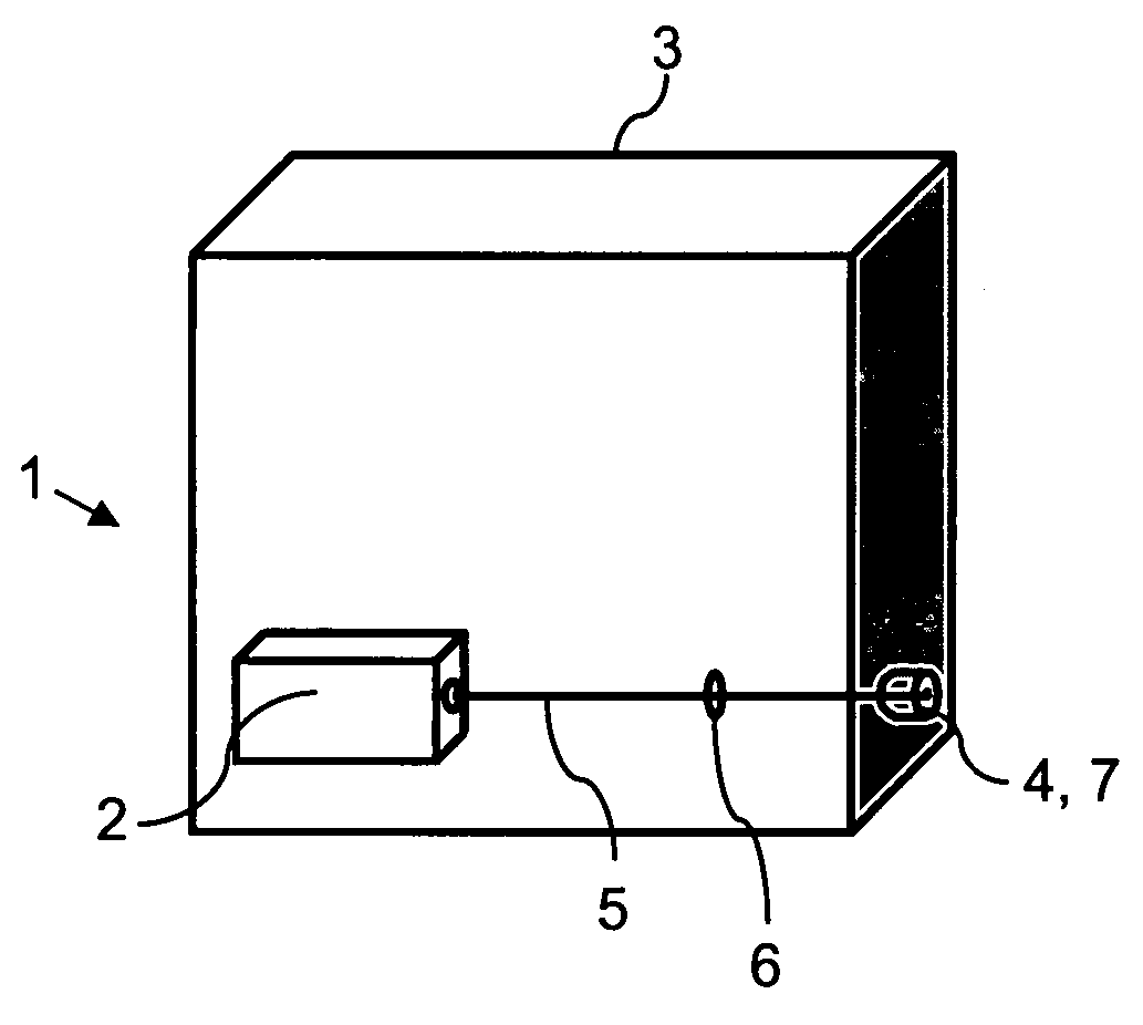
[0018] The module could have a housing that then defines the module dimensions which are advantageously adapted to the size of the slots. With an eye towards achieving high flexibility, each individual module could be encapsulated in such a way that it forms an opto-mechanical unit which, in a simple manner, can be mechanically inserted or slid into one of the slots of the docking station.

[0019] Each module could have its own power / control unit integrated into the module. In order to attain a cost reduction as well as a low-maintenance design, however, preference is given to a central power / control unit that can be brought int...


PUM


Abstract

A device for generating a laser light beam includes a module. The module includes at least one laser light source, and a mechanical, an electrical and/or an optical interface defined towards an outside of the module.

Description

[0001] Priority is claimed to provisional application 60 / 532,672, filed Dec. 23, 2003, to German patent application DE 103 61 177.0, filed Dec. 22, 2003, and to German patent application DE 103 59 012.9, filed Dec. 15, 2003, the subject matter of each of which is hereby incorporated by reference herein.[0002] The present invention relates to a device for generating a laser light beam, particularly an illuminating light beam for a preferably confocal scanning microscope, having at least one source of laser light. BACKGROUND [0003] A number of variants of devices for generating a laser light beam have been known in actual practice for years. Merely by way of an example, mention is made here of German patent DE 196 33 185 C2, which discloses a polychromatic point light source for a laser scanning microscope. Here, the radiation from a total of four sources of laser light is coaxially combined by means of a recombiner unit. Via an appropriate connection, an optical fiber leads to a lase...

Claims


Application Information

Patent Timeline
Patent Type & Authority Applications(United States)
IPC IPC(8): H01S3/02H01S3/09H01S3/23
CPCG01N21/6458G01N2201/024H01S3/2383H01S3/02G02B21/0032
Inventor SEYFRIED, VOLKERSTORZ, RAFAEL
Owner LEICA MICROSYSTEMS CMS GMBH
Why Eureka
Try Eureka