RF Plasma Source With Conductive Top Section

Inactive Publication Date: 2005-09-22
VARIAN SEMICON EQUIP ASSOC INC
View PDF47 Cites 80 Cited by
  • Summary
  • Abstract
  • Description
  • Claims
  • Application Information

AI Technical Summary

Problems solved by technology

The secondary electrons tend to heat and to charge the chamber tops, whi

Method used


Image

  • RF Plasma Source With Conductive Top Section
  • RF Plasma Source With Conductive Top Section
  • RF Plasma Source With Conductive Top Section

Examples


Embodiment Construction

[0014] A plasma source of the present invention provides a uniform ion flux and also dissipates the effects of secondary electrons. Some aspects of the plasma source of the present invention are described in connection with plasma doping for the purpose of illustrating the invention. However, it is understood that the plasma source of the present invention has many applications and is not limited to plasma immersion sources for plasma doping.

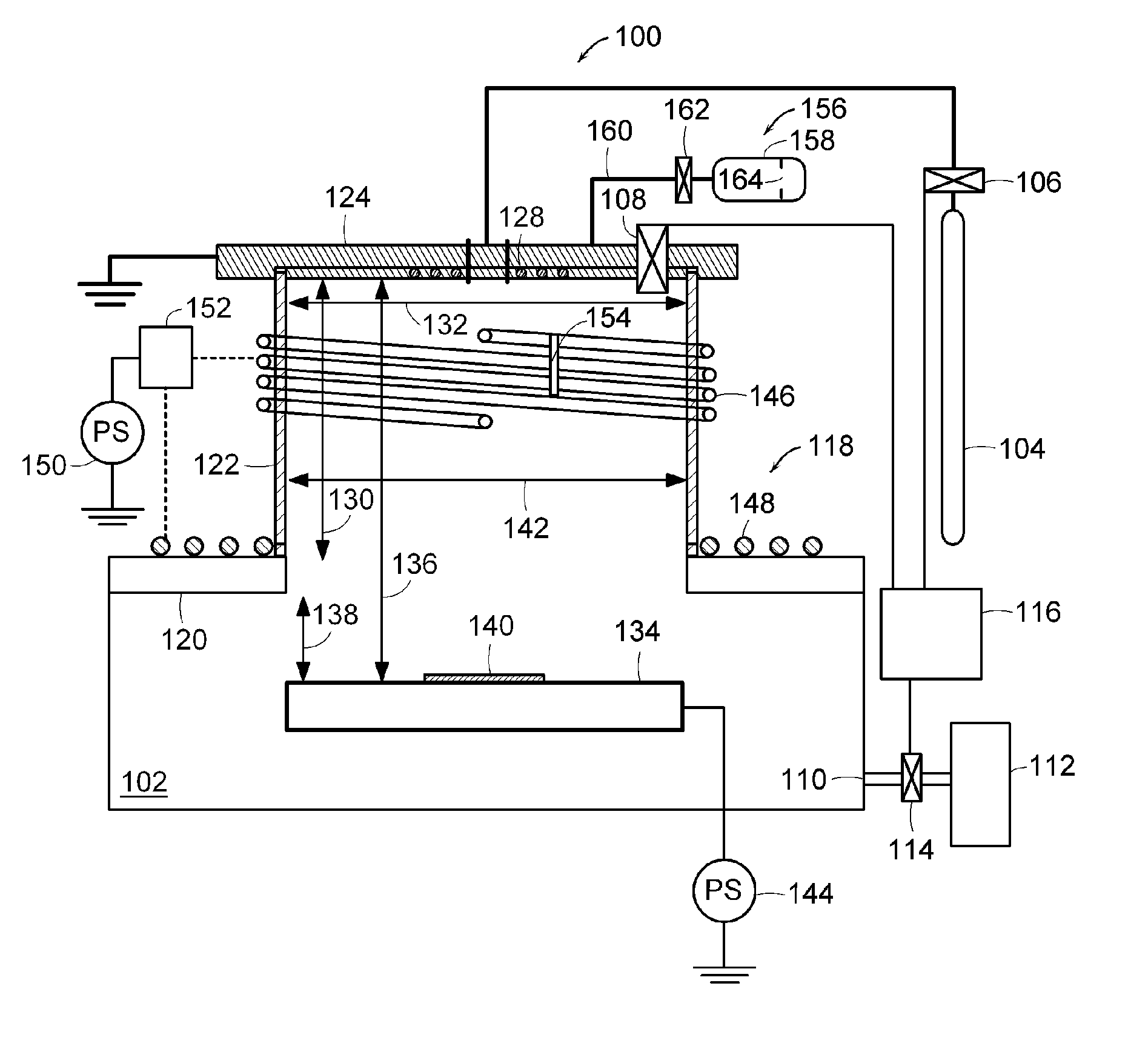
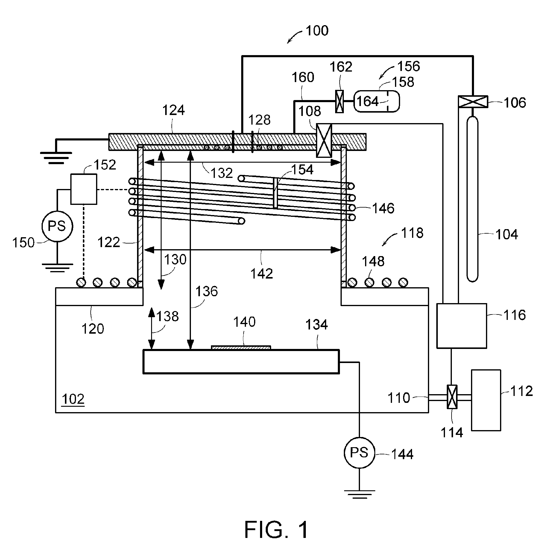
[0015]FIG. 1 illustrates a RF plasma source 100 having vertical and horizontal RF coils and a conductive top section according to the present invention. The plasma source 100 includes a chamber 102 that contains a process gas. A gas source 104 that is coupled to the chamber 102 through a proportional valve 106 supplies the process gas to the chamber 102. A pressure gauge 108 measures the pressure inside the chamber 102. An exhaust port 110 in the chamber 102 is coupled to a vacuum pump 112 that evacuates the chamber 102. An exhaust valve 114 co...


PUM

PropertyMeasurementUnit
Temperatureaaaaaaaaaa
Lengthaaaaaaaaaa
Currentaaaaaaaaaa

Abstract

A plasma source includes a chamber that contains a process gas. The chamber has a chamber top comprising a first section formed of a dielectric material that extends in a horizontal direction. A second section of the chamber top is formed of a dielectric material that extends a height from the first section in a vertical direction. A top section of the chamber top is formed of a conductive material that extends a length across the second section in the horizontal direction. A radio frequency antenna is positioned proximate to at least one of the first section and the second section. The radio frequency antenna induces radio frequency currents into the chamber that excite and ionize the process gas so as to generate a plasma in the chamber.

Description

RELATED APPLICATION SECTION [0001] This application is a continuation-in-part of U.S. patent application Ser. No. 10 / 805,966, filed Mar. 22, 2004 entitled “Plasma Immersion Ion Implantation Apparatus and Method,” the entire application of which is incorporated herein by reference.INTRODUCTION [0002] The section headings used herein are for organizational purposes only and are not to be construed as limiting the subject matter described in any way. [0003] The present invention relates to plasma sources. Plasma sources are commonly used in the semiconductor industry and other industries for performing etching and deposition. Plasma immersion systems immerse a substrate or target in a plasma for processing. The substrate or target is biased with respect to the plasma potential in order to attract ions for processing. [0004] Recently plasma immersion systems have been used for performing ion implantation of semiconductor wafers. Ions are not accelerated toward the wafer like in conventi...

Claims


Application Information

Patent Timeline
IPC IPC(8): H01J37/32
CPCH01J37/32412
Inventor SINGH, VIKRAMPERSING, HAROLDMILLER, TIMOTHY
Owner VARIAN SEMICON EQUIP ASSOC INC
Why Eureka
Try Eureka