

Polarizer and liquid-crystal display apparatus
- Summary
- Abstract
- Description
- Claims
- Application Information
AI Technical Summary
Benefits of technology
Problems solved by technology
Method used
Image

Examples
embodiment
[0117] Hereafter, the contents of the invention of the present application will be described in more detail along the following examples. Th embodiment describes the concrete examples of the present invention but does not define the invention. The embodiment may include the numerical values calculated by the optical simulation through the use of the 44 matrix disclosed in Japan Society of Applied Physics, Optic Conference, “Crystal Chemical” Chapter 5, Pages 102 to 163, issued in the fourth print of the first edition in 1984 and published by Morikita Publishing Ltd. Herein, for the simulation are used the spectral characteristic between three-wavelength cold cathodes and spectral transmission characteristics of the R, G and B color filters. For the polarization layer of the polarizer is used the spectral characteristic of 1224 DU manufactured by Nitto Denko, Ltd. For the wavelength dispersion of the retardation films, polycarbonate (PC), polystyrene, norbornane system materials are ...
example 1
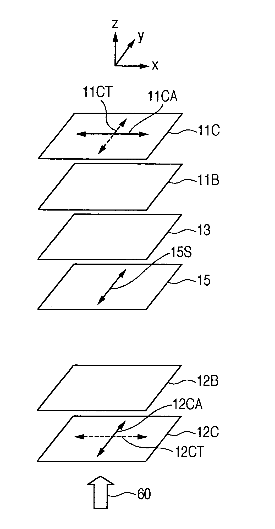
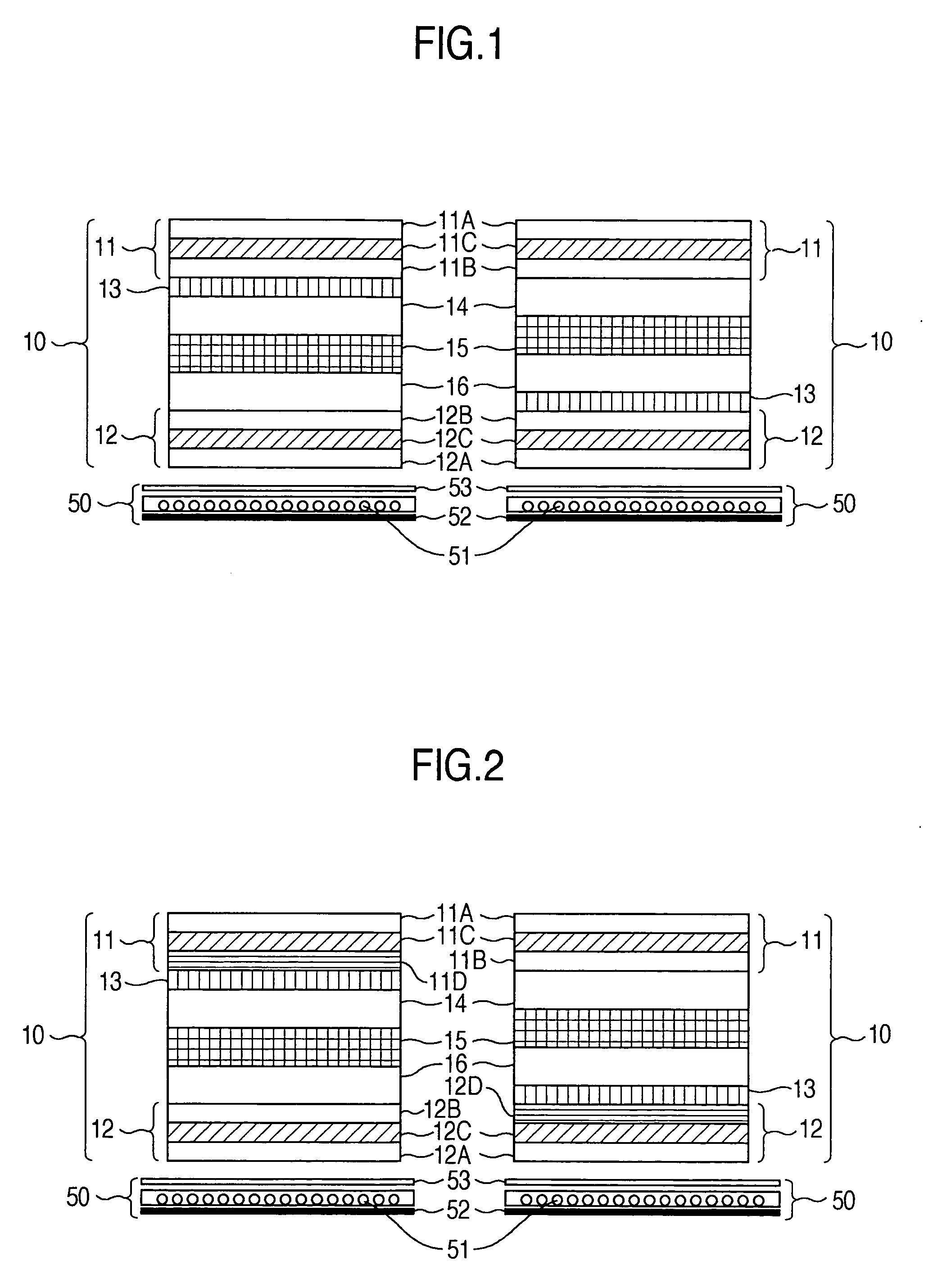
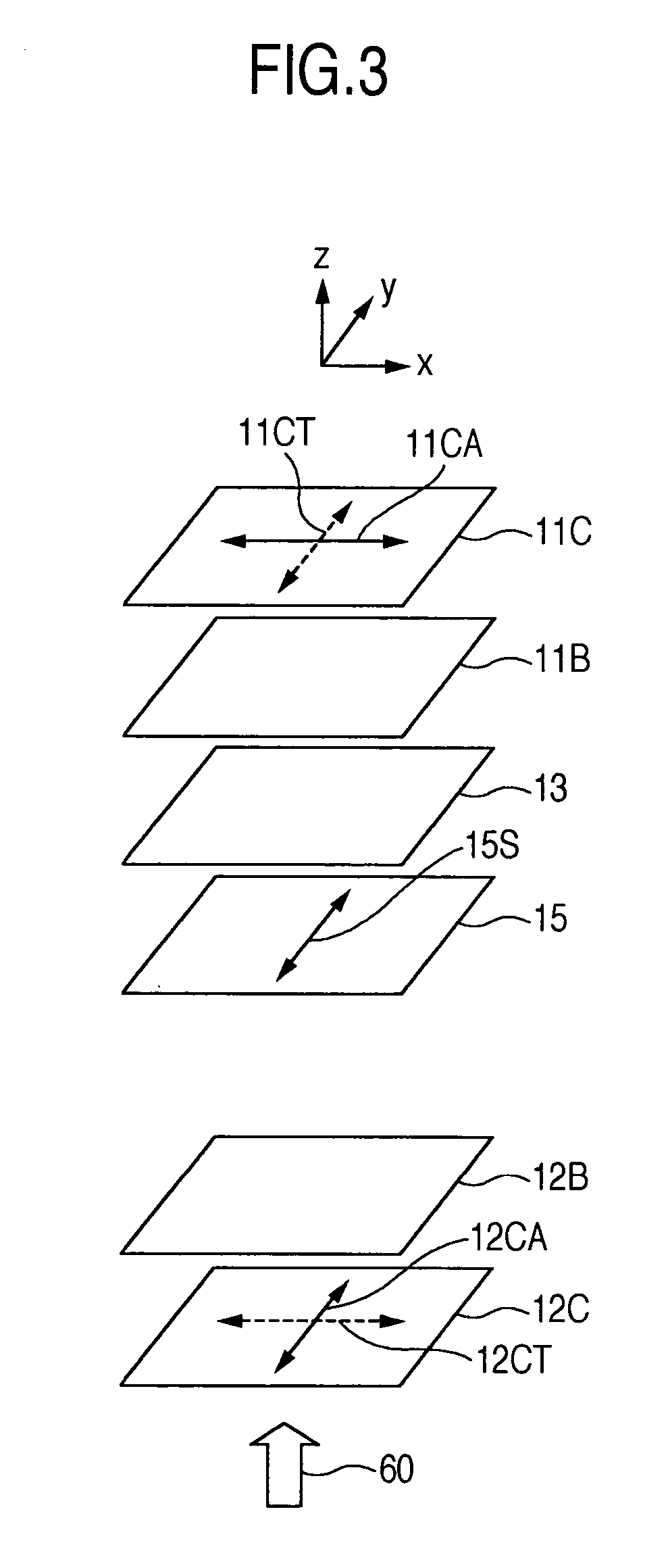
[0131] The structure of the example 1 is shown in FIG. 1 and the optical configuration thereof is shown in FIG. 16, in which the left-hand portion concerns with the o-mode and the right-hand portion concerns with the e-mode. In the example 1, one positive c-plate and one positive a-plate are used as the retardation films. Herein, the film in which the refractive index on the plane is isotropic and the refractive index in the thickness direction is larger is called the positive c-plate. According to the expression (3), the retardation R·h may be represented as
nz>nx≈ny
R·h=(nz−(nx+ny) / 2)·h (5)
[0132] Afterwards, the retardation of the positive c-plate indicates this retardation in the thickness direction. In FIG. 16, 13C1 denotes the positive c-plate and 13A1 denotes the positive a-plate. 13A1S denotes the slow axis direction of the positive a-plate. According to the inventors' study, as shown in FIG. 16, for the o-mode, it is necessary to locate the slow axis 13A1S of the positive ...
example 2
[0142] The structure of the example 2 is shown in FIG. 1 and the optical configuration thereof is shown in FIG. 25, in which the left-hand portion concerns with the o-mode and the right-hand portion concerns with the e-mode. In the example 2, one negative c-plate and one negative a-plate are used as the retardation films. Herein, the film in which the refractive index is isotropic on the plane and the refractive index in the thickness direction is small is called the negative c-plate. According to the expression (3), the retardation R·h may be represented as follows. Afterwards, the retardation of the negative c-plate indicates the retardation in the thickness direction.
nz≦nx≈ny
R·h=((nx+ny) / 2−nz)·h (6)
Further, the film in which the refractive index is anisotropic on the plane and the refractive index in the thickness direction is substantially equal to a larger one of the planar refractive index is called the negative a-plate. According to the expression (4), the retardation ma...
PUM
 Abstract
Description
Claims
Application Information