High-speed serial link clock and data recovery

a serial link and clock technology, applied in the field of high-speed serial link clock and data recovery, can solve the problems of inefficient bandwidth utilization, disadvantageous processing approaches in data transmission, and high frequency phase jitter tracking in high-speed data recovery systems

Inactive Publication Date: 2005-09-22
IND TECH RES INST
View PDF14 Cites 17 Cited by
  • Summary
  • Abstract
  • Description
  • Claims
  • Application Information

AI Technical Summary

Benefits of technology

[0010] To achieve these and other advantages, and in accordance with the purpose of the present invention as embodied and broadly described, there is provided a system comprising a clock for generating a clock signal at half a rate of transmitted serial data; a half-rate phase detector for oversampling transmitted serial data and providing sampled data, and for detecting phase transitions between a phase lead and a phase lag in the sampled data and output phase transition data; an encoder for encoding the phase transition data; a confidence counter coupled to receive the phase transition data and provide an output representative of an accumulated effect of the phase transitions; and a phase selector, coupled to receive the clock signal and the output from the confidence counter, for selecting an optimum phase effective for recovering the clock relative to the transmitted serial data.
[0011] Also in accordance with the present invention, there is provided a clock and data recovery (“CDR”) method comprising generating a clock signal at half a rate of transmitted serial data, oversampling the transmitted serial data and providing sampled data, detecting phase transitions between a phase lead and a phase lag in the sampled data and outputting phase transition data, encoding the phase transition data, providing an output representative of an accumulated effect of the phase transitions, and selecting an optimum phase effective for recovering the clock relative to the transmitted serial data.

Problems solved by technology

The PLL, however, may have problems tracking high frequency phase jitter in high-speed data recovery systems.
Such processing approaches in data transmission are disadvantageous because of their excessive power consumption and inefficient utilization of bandwidth over the communications link.
Moreover, conventional CDR methods are not suited for making fast data recovery decisions.

Method used


Image

  • High-speed serial link clock and data recovery
  • High-speed serial link clock and data recovery
  • High-speed serial link clock and data recovery

Examples


Embodiment Construction

[0022] Reference will now be made in detail to present embodiments of the present invention, examples of which are illustrated in the accompanying drawings. Wherever possible, the same reference numbers will be used throughout the drawings to refer to the same or like parts.

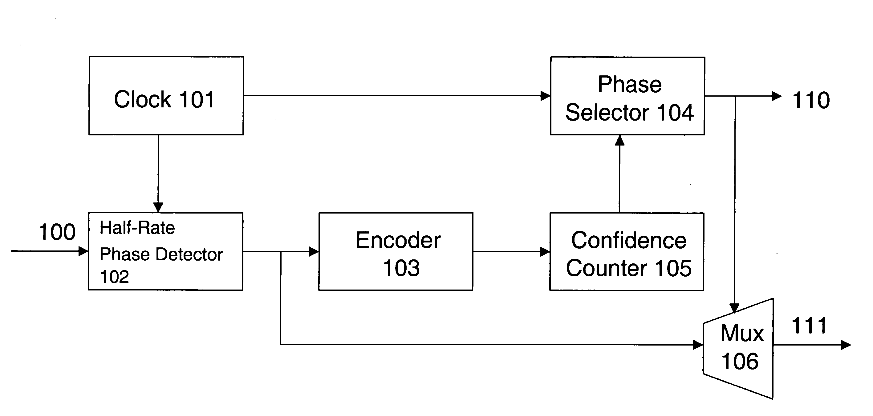
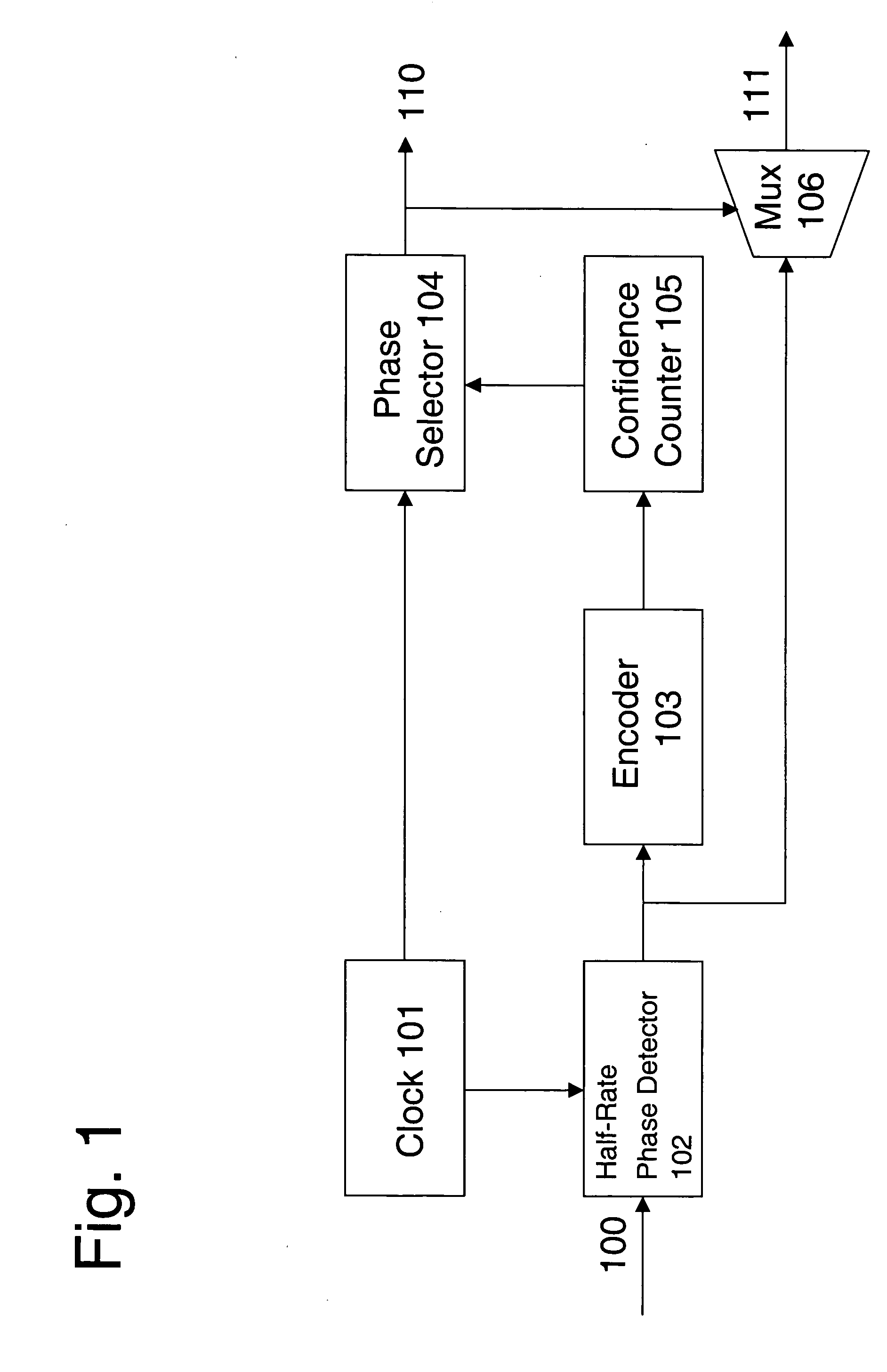
[0023]FIG. 1 is a block diagram of a system for clock and data recovery (“CDR”) according to one embodiment of the present invention. The system comprises a clock generator 101, a half-rate phase detector 102 receiving input data 100, an encoder 103, a phase selector 104 outputting a recovered clock 110, a confidence counter 105, and a multiplexer 106 outputting recovered data 111.

[0024] Based on a reference clock, clock generator 101 generates an 8-phase clock signal for input data 100 at half of the input data rate. The clock signal includes 8 phases for each clock period. A delay locked loop (“DLL”) or phase locked loop (“PLL”) device can serve as an 8-phase clock of clock generator 101. A crystal oscillator...


PUM


Abstract

A system for clock and data recovery (“CDR”) includes a clock generator, a half-rate phase detector for receiving the input data, an encoder, a phase selector outputting recovered clock, a confidence counter, and a multiplexer outputting recovered data. The clock generator generates an 8-phase clock signal at half a rate of the transmitted serial data. The phase detector samples input data at four times the standard sampling rate, takes the oversampled data and detects phase transitions therein, i.e., phase lead and lag. The encoder encodes the phase transition data. The confidence counter receives the phase transition data and generates a signal representing the accumulated net effect of the phase transitions. The phase selector receives the confidence counter signal and the 8-phase clock from the clock generator, and determines the optimum phase for data sampling.

Description

BACKGROUND OF THE INVENTION [0001] 1. Field of the Invention [0002] The present invention generally relates to data processing systems and, more particularly, to the transmission of data over a serial line or link between two subsystems of a data processing system. [0003] 2. Description of the Related Art [0004] Communications networks can provide high bit-rate transport over a shared medium with a serial line or link, such as passive optical networks, cable television networks (fiber, coaxial or hybrid), digital television, and wireless networks. These shared-medium networks typically use time, frequency or code division multiplexing to transport data signals from a central terminal to several remote customer terminals and time division multiple access (TDMA) to transport data signals from the customer terminals to the central terminal. TDMA is characterized by noncontinuous or burst mode data transmission. [0005] Traditional clock and data recovery (“CDR”) methods are provided for...

Claims


Application Information

Patent Timeline
Patent Type & Authority Applications(United States)
IPC IPC(8): H04L7/00H04L7/033
CPCH04L7/005H04L7/0338
Inventor SU, CHAU-CHINLEE, CHIEN-HSILU, HUNG-WENLIN, HSUEH-CHINTSENG, YEN-PINWANG, CHIA-NANLIU, UAN-JIUN
Owner IND TECH RES INST
Why Eureka
Try Eureka