Microphone and method of producing a microphone

a microphone and microphone technology, applied in the direction of electrical transducers, transducer types, piezoelectric/electrostrictive transducers, etc., can solve the problems of increasing production costs, increasing production costs, and difficult to accommodate a plurality of microphones including the downstream circuit elements in a miniaturized arrangement, so as to increase the automation degree of production method, increase the cost efficiency of production method, and increase the effect of automation degr

Inactive Publication Date: 2005-09-22
INFINEON TECH AG
View PDF9 Cites 172 Cited by
  • Summary
  • Abstract
  • Description
  • Claims
  • Application Information

AI Technical Summary

Benefits of technology

[0024] Another advantage of the invention is the possibility to machine the impedance hole increasing the automation degree of the production method.
[0025] The generation of a directional sensitivity characteristic by an impedance hole which is easy to produce also increases the cost efficiency of the production method.
[0026] As the impedance of the impedance hole depends on its geometric dimensions, there is an increased flexibility in the design of the directional sensitivity characteristic allowing the manufacturers to adapt a design concept to various usage requirements only by adapting the dimensions of an impedance hole.
[0027] This flexibility in the directional sensitivity characteristic may even be increased by an implementation of further impedance holes which are easy to produce and also influence the directional characteristic behavior. Therefore it is even

Problems solved by technology

However, a complex structure with several microphones and a complex downstream circuit forming, for example, the difference of the microphone signals is required for this.
This use of several microphones, particularly also of additional electronic circuit elements, raises production costs.
Furthermore, it is difficult to accommodate a plurality of microphones including the downstream circuit elements in a miniaturized arrangement, such as for microphones in a mobile phone application or hearing aid application.
Thus it is also dif

Method used


Image

  • Microphone and method of producing a microphone
  • Microphone and method of producing a microphone
  • Microphone and method of producing a microphone

Examples


first embodiment

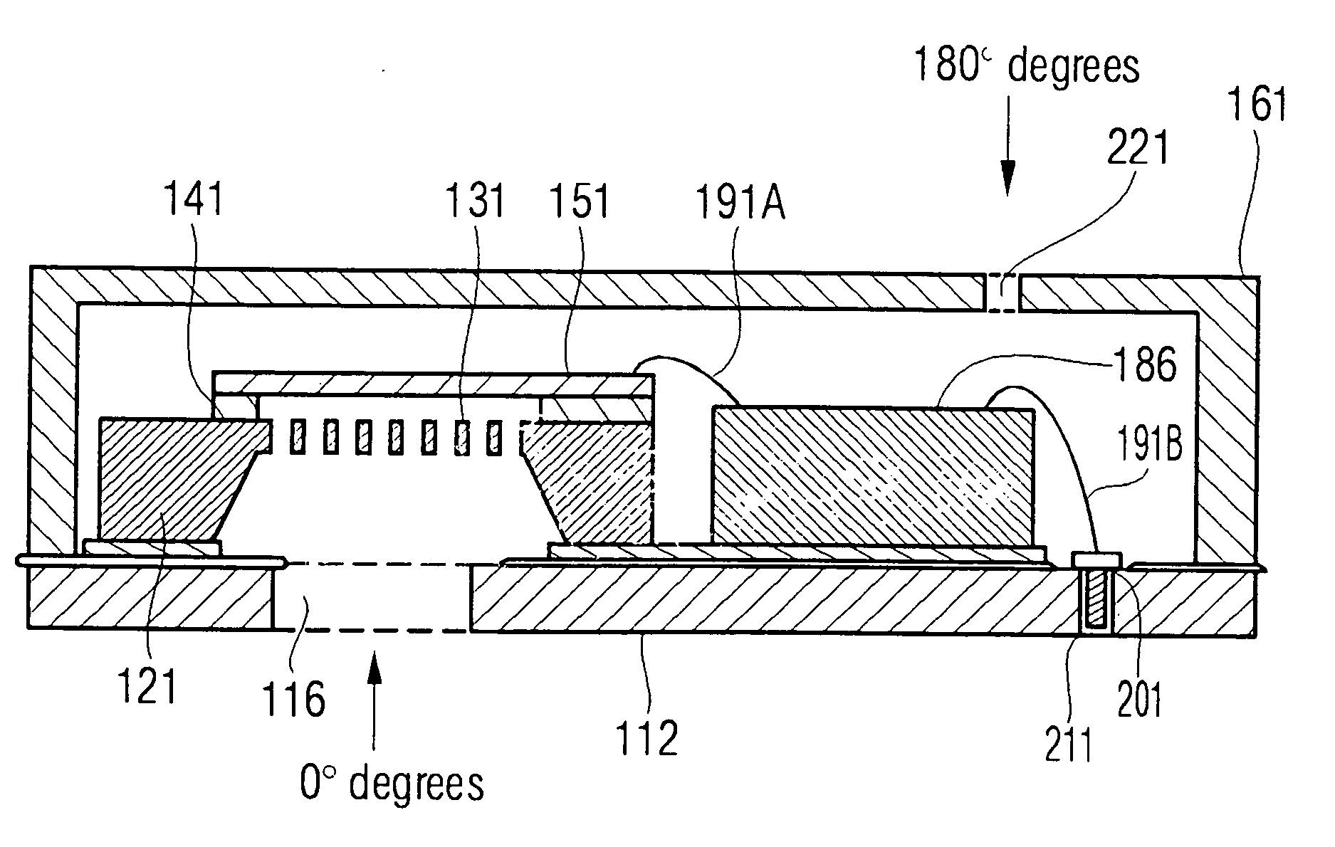
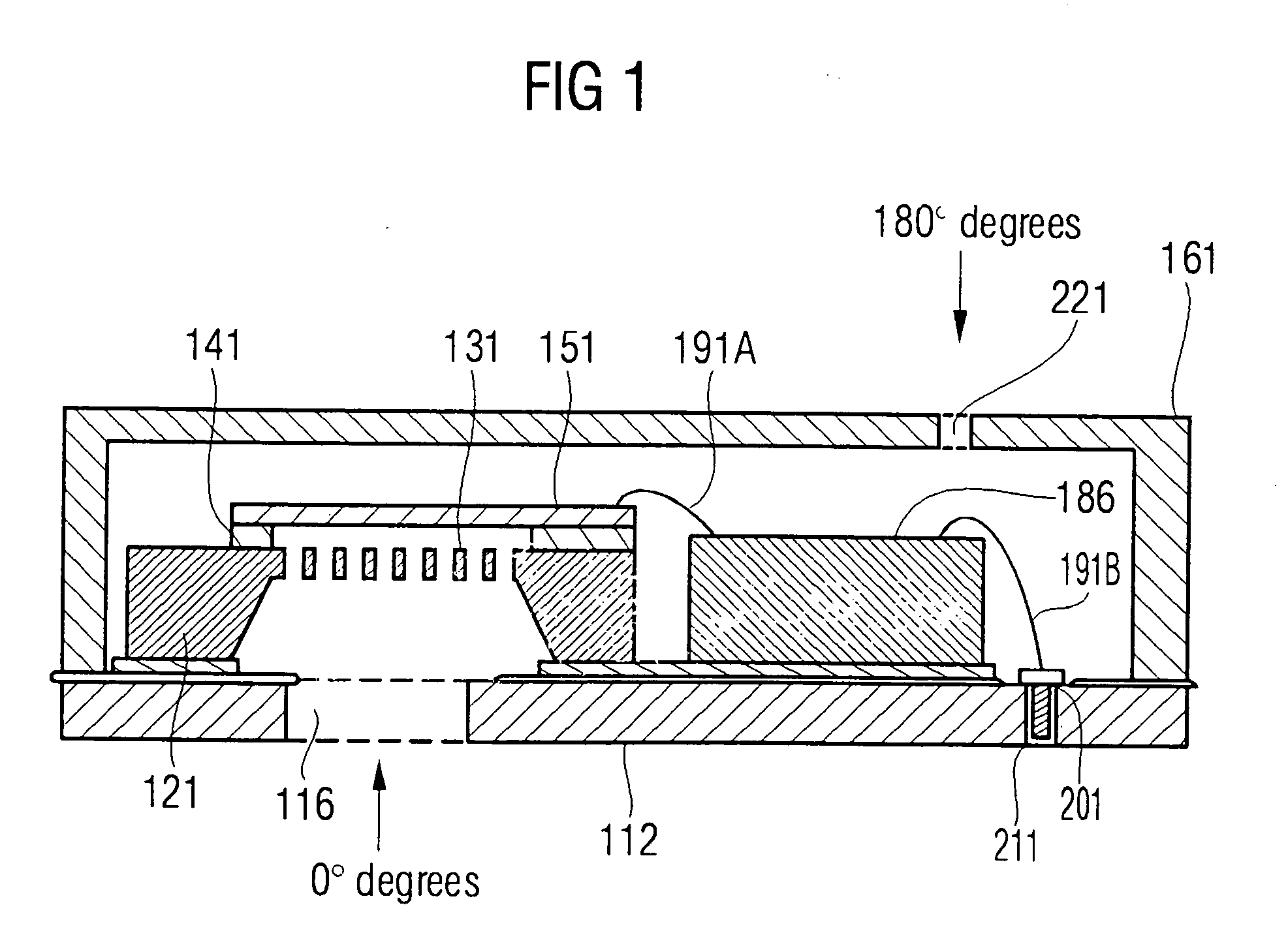
[0055] Unlike the invention in FIG. 1, the microphone now comprises several impedance holes 221. The result is again an acoustic RC element now formed of the impedance holes 221 having a high acoustic resistance and the interior of the housing. The interior of the housing again functions as acoustic capacitance. The acoustic resistance of the impedance holes 221 is formed by the flow resistance of the impedance holes 221 which are preferably implemented with small geometric dimensions as compared to the sound hole 116.

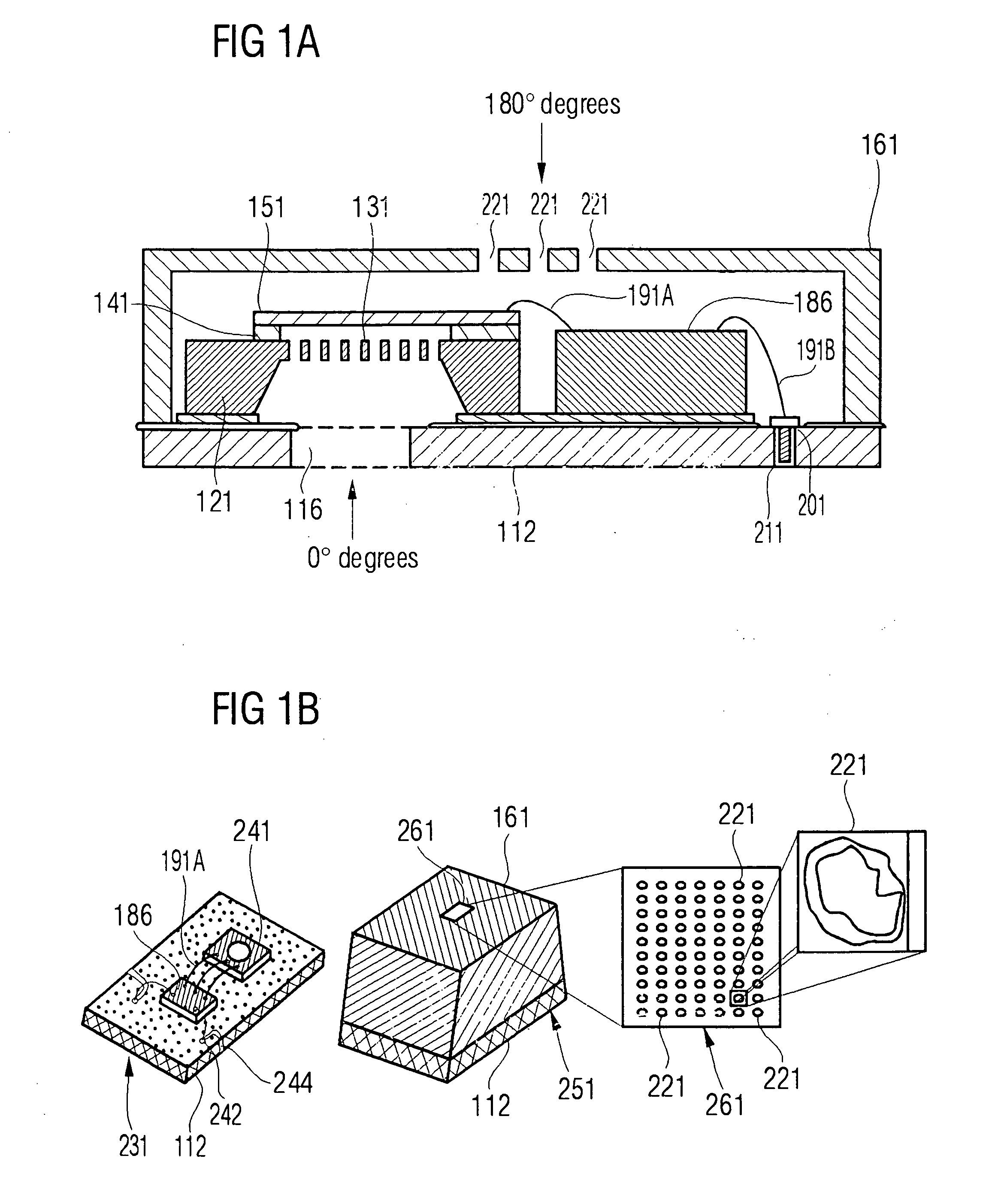
[0056] A produced illustration of the embodiment of the invention discussed in FIG. 1a is explained by FIG. 1b. From left to right, it shows a substrate illustration 231, an overall illustration 251, an impedance hole region 261 and the impedance hole 221 in schematic illustration.

[0057] The substrate illustration 231 shows an embodiment of the substrate 112, the signal processing chip 186, the bond wires 191a, a microphone chip 241, a contact 242 and a contacting 244...

embodiment 281

[0064]FIG. 2b shows a schematic illustration of the embodiment according to the present invention explained in FIG. 2a. From left to right, there can be seen a premold substructure 271, a housing embodiment 281 and the impedance hole region 261.

[0065] The premold substructure 271 contains the microphone chip 241 and the signal processing chip 186 and is provided with contacts 191d leading to the outside. By means of those, the premold substructure is connected in a mechanical and electrically conductive way to a board not shown here.

[0066] The housing embodiment 281 also comprises the contacts 191d to the board and, in addition, includes the impedance hole region 261.

[0067] The impedance hole region261 is shown projected out in the arrangement on the right. Again the impedance holes 221 are apparent. The task of the impedance holes 221 and the impedance hole region 261 is to form an acoustic resistance forming an acoustic RC element with the interior of the premold housing 281.

[0...


PUM


Abstract

A microphone has a substrate including an acoustically transparent substrate region, a lid with an acoustically transparent lid region, and a membrane which is held by a membrane carrier between the lid and the substrate. The acoustically transparent substrate region or the acoustically transparent lid region is provided with at least one impedance hole sized so that an acoustic impedance of the impedance hole is larger than an acoustic impedance of the acoustically transparent region of the respective other region of substrate region and lid region.

Description

CROSS-REFERENCE TO RELATED APPLICATION [0001] This application claims priority from German Patent Application No. 10 2004 011 149.9, which was filed on Mar. 8, 2004, and is incorporated herein by reference in its entirety. BACKGROUND OF THE INVENTION [0002] 1. Field of the Invention [0003] The present invention relates to a microphone and a method for producing a microphone and, in particular, to a microphone with directional sensitivity characteristic. [0004] 2. Description of the Related Art [0005] More and more, microphones performing the conversion of an acoustic signal to an electric signal are used in technical devices. An increasing improvement of the processing of voice signals in means downstream with respect to the microphones, such as digital signal processors, requires the properties of the microphones to be improved also, because the quality of voice transmission continues to improve. In addition, microphones are increasingly used in portable devices, such as mobile pho...

Claims


Application Information

Patent Timeline
IPC IPC(8): H04R1/34H04R19/01H04R19/04H04R25/00H04R31/00
CPCH04R19/04H01L2224/48091H01L2224/48137H01L2924/3011H01L2924/00014H01L2924/00
Inventor DEHE, ALFONSFUELDNER, MARC
Owner INFINEON TECH AG
Why Eureka
Try Eureka