Electrostatic method and device to increase power output and decrease erosion in steam turbines

a technology of steam turbines and electric motors, which is applied in the direction of machines/engines, mechanical equipment, liquid fuel engines, etc., can solve the problems of reducing the energy conversion efficiency of the turbine, damaging the blades by erosion, etc., and achieves the effect of reducing the subcooling, enhancing condensation inside the turbine, and reducing the average size of water droplets present in the steam

Inactive Publication Date: 2005-09-22
TARELIN ANATOLY OLEKSIOVYCH +2
View PDF5 Cites 19 Cited by
  • Summary
  • Abstract
  • Description
  • Claims
  • Application Information

AI Technical Summary

Benefits of technology

[0030] The essence of the present invention lies in adding electric charge to the steam before it reaches the saturation line in a low pressure steam turbine in order to provide abundant condensation nuclei within the phase transition zone. The source of charge is an array of corona electrodes preferably installed inside the LP turbine just before the saturation line, or at some point upstream of the LP turbine blades. Injecting electric charge into the steam at any of these locations will provide some concentration of charged particles within the phase transition zone. The large concentration of nuclei thus provided within the phase transition zone greatly enhances condensation inside the turbine, whereby subcooling is decreased and the average size of water droplets present in the steam becomes much smaller. These changes increase power output and decrease erosive damage to the blades, nozzles and diaphragms in the low pressure part of the turbine. Further benefit may be obtained if the electric charge present in the steam flowing out of the turbine is removed using the “spikes” described by Tarelin et al. in U.S. Pat. No. 6,698,205; that is, if the two inventions are installed and used together.
[0032] Finally, this invention can be used in connection with turbines that use a working fluid other than steam; for example, ammonia, ammonia-water or a volatile fluorocarbon. The only essential requirement is that a saturation line be located within the turbine, whereby the working fluid flowing out of the turbine would contain some amount of dispersed liquid phase if it approached thermodynamic equilibrium. In any such turbine—regardless of working fluid—introducing electrically charged particles into the phase transition zone will tend to increase power output and decrease erosion by liquid droplets.

Problems solved by technology

These coarse drops provide few nuclei for condensation, and impinge upon the following turbine blades, decreasing the energy conversion efficiency of the turbine and damaging the blades by erosion.

Method used


Image

  • Electrostatic method and device to increase power output and decrease erosion in steam turbines
  • Electrostatic method and device to increase power output and decrease erosion in steam turbines
  • Electrostatic method and device to increase power output and decrease erosion in steam turbines

Examples


example 2

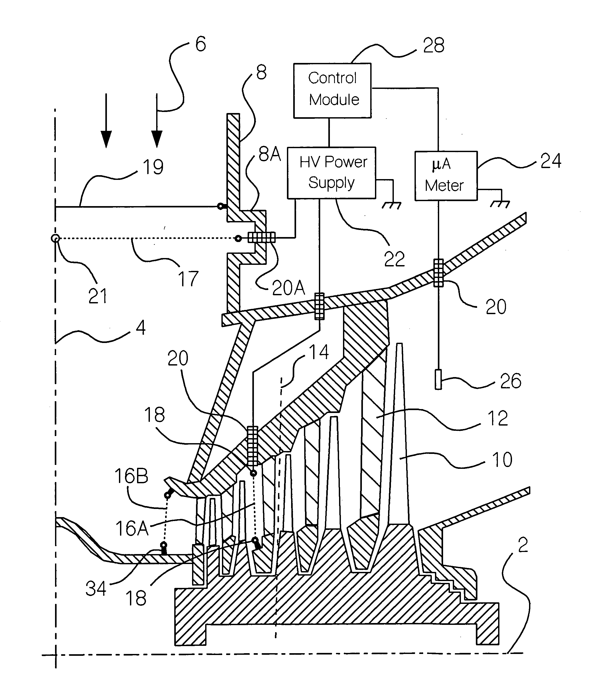
[0079] An existing LP turbine can most easily be provided with this invention by installing corona electrodes 17 inside steam pipe 8 just before it connects to the steam chest of the LP turbine. This installation can be realized with no modifications to the turbine itself. Preferably, three corona electrodes 17 are installed in a coplanar disposition, spaced at 120° apart and electrically interconnected at crossing point 21. Corona electrodes 17 are suspended between insulators 20A which are preferably mounted inside recesses 8A in the wall of steam pipe 8 to shield them from direct impact of the steam flow and minimize drag. At least one of insulators 20A must be a feed-through insulator, allowing an electrical connection of corona electrodes 17 to high voltage power supply 22.

[0080] Optionally, grounded counterelectrodes 19 are installed upstream of corona electrodes 17 and in parallel with them to even out the electric field intensity and promote an even distribution of corona d...

example 3

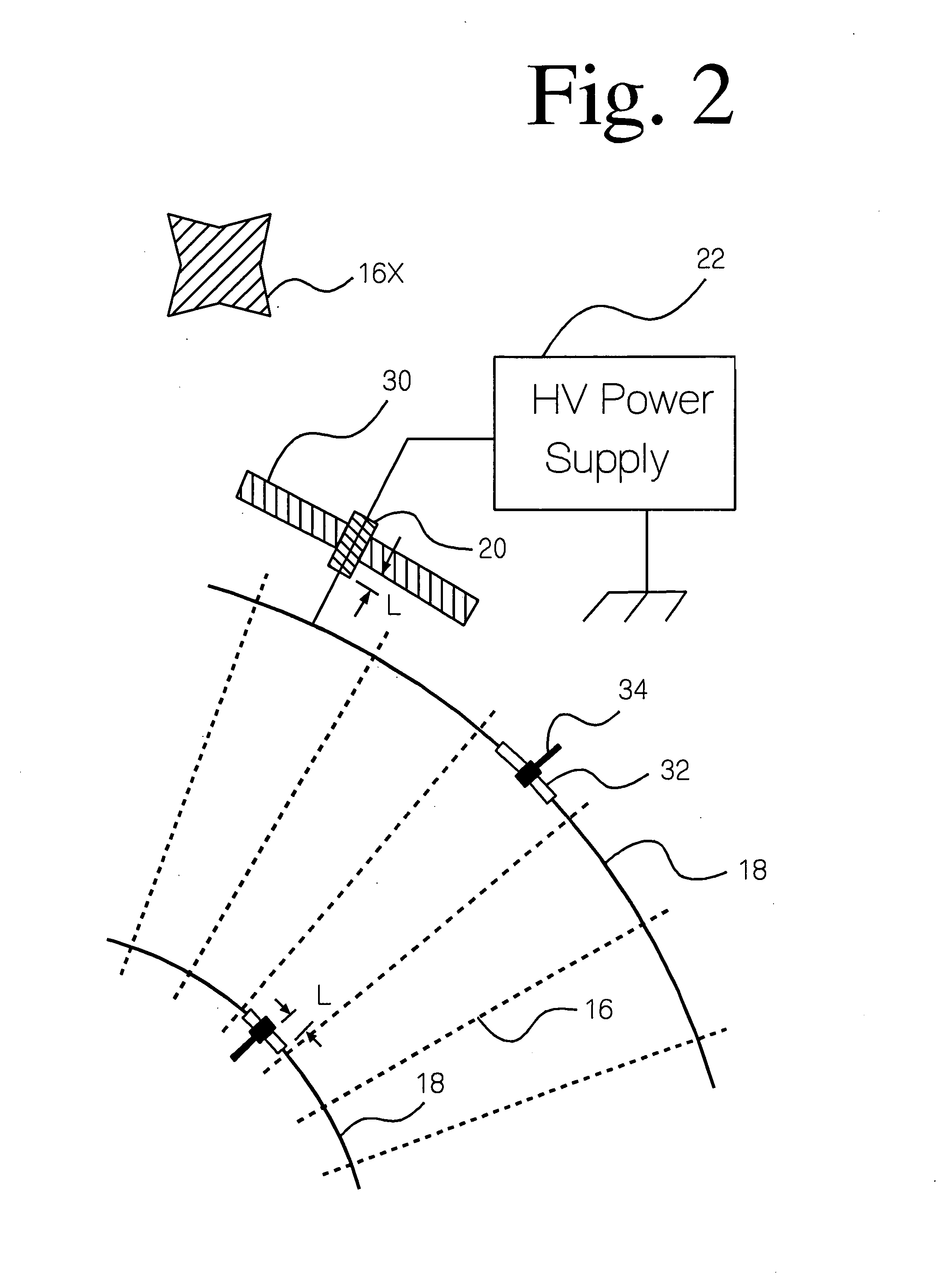
[0083] Corona electrodes can be installed at another location before the LP turbine blades, for example semirigid corona electrodes 16B installed just before the steam enters the blades of the LP turbine. The construction illustrated in FIG. 2 is suitable for this location as well, but high activity semirigid electrodes must be used because of the high steam density; for example, a linear metallic brush, or a serrated strip. To provide an even distribution of charge, the distance between the midpoints of adjacent electrodes should be no greater than the distance from the electrodes to the first row of turbine blades or the first diaphragm encountered by the steam. Thirty-six semirigid electrodes 16 attached to two collector rings 18 would be appropriate for the location depicted in FIG. 2. The specification for high voltage power supply 22 needed to power corona electrodes 16B would be the same as needed to power corona electrodes 17.


PUM


Abstract

The wet steam exiting a low pressure steam turbine does not rapidly attain thermodynamic equilibrium because insufficient condensation nuclei are present in the phase transition zone inside the turbine. Therefore, the steam is subcooled, decreasing the power generated by the turbine, and the liquid water carried by the steam consists of relatively coarse droplets which strike the surface of the turbine blades causing erosion. Corona electrodes installed inside the turbine before the saturation line create electrically charged particles which serve as condensation nuclei, decreasing subcooling, and producing a large number of fine droplets. Thereby, thermodynamic equilibrium is more closely approached, more power is generated, and smaller water droplets cause less erosion inside the turbine.

Description

[0001] Priority is claimed based on U.S. Provisional Patent Application 60 / 535,905 which was filed 12 Jan. 2004.FIELD OF INVENTION [0002] This invention is related to energy conversion efficiency and reliability of steam turbines. A method and device are provided which decrease subcooling of steam in the low pressure part of the turbine and also decrease the number of large water droplets produced, whereby the energy conversion efficiency of the turbine is increased, and erosion of the turbine blades and diaphragms by impinging water droplets is decreased. PRIOR ART [0003] It is known in the art that the enthalpy of wet steam in the low pressure part of a turbine can be increased by heating the stationary blades or diaphragms with superheated steam that is provided through special channels inside the stationary blades (“The efficiency of the wet steam stages of a turbine with heated stationary blades.”Trudy Moskovskogo Energeticheskogo Instituta, 663, pp. 48-56, 1993). Increasing th...

Claims


Application Information

Patent Timeline
Patent Type & Authority Applications(United States)
IPC IPC(8): F01D25/00F01D25/30F01D25/32F01K7/16F01K9/00F01K13/02
CPCF01D25/007F01D25/305F05D2210/20F01K7/16F01K9/00F01D25/32
Inventor TARELIN, ANATOLY OLEKSIOVYCHSKLIAROV, VOLODYMYR PETROVYCHWERES, OLEH
Owner TARELIN ANATOLY OLEKSIOVYCH
Why Eureka
Try Eureka