Battery pack of improved structure

a battery pack and structure technology, applied in the direction of cell components, electrochemical generators, secondary cells servicing/maintenance, etc., can solve the problems of deterioration of the flow of resin, insufficient strength, and reduced yields

Active Publication Date: 2005-09-22
LG ENERGY SOLUTION LTD
View PDF11 Cites 102 Cited by
  • Summary
  • Abstract
  • Description
  • Claims
  • Application Information

AI Technical Summary

Benefits of technology

[0010] Therefore, the present invention has been made in view of the above problems, and it is an object of the present invention to provide a battery pack, designed to be lighter, compacter and miniaturized, thereby allowing an electronic device employing the battery pack to be reduced in overall size, enhancing workability through a simplified assembling process, reducing manufacturing costs through reduction of the number of components, and enhancing productivity through reduction of the number of operating steps by eliminating additional installation steps.
[0012] According to the present invention, the electrical connection between the battery cell and the PCM block can be easily performed through the connecting hole perforated through the PCM block, thereby providing various advantages as described above.
[0014] The PCM block acts to prevent overcharge, over-discharge, over-current and the like of the battery cell through detection for a condition of the battery cell. The PCM block may comprise a PCM assembly having a protective circuit formed thereon to provide a function of preventing overcharge, over-discharge and over-current of the battery cell; a cap housing surrounding the PCM assembly to hold the PCM assembly therein; and electrode lids attached to the PCM assembly while being electrically connected to electrode terminals of the battery cell. In this construction, the electrode lids are connected to a lower surface of the PCM assembly to provide the electrically connected portion between the battery cell and the PCM block, and the connecting hole is perforated through the PCM assembly and the cap housing of the PCM block such that the electrode lids are exposed to the outside of an upper surface of the cap housing. The PCM assembly is provided on an upper surface with external input and output terminals, and the cap housing is provided with a window for terminals such that the external input and output terminals can be exposed to the outside of the upper surface through the window. The electric lids are not limited to any particular construction so long as the PCM assembly can be electrically connected to the battery cell through the electric lids in a state of being attached to the PCM assembly. Preferably, a well-known nickel plate may be used for the electric lids.
[0018] As for a preferred embodiment of the invention, a battery pack may be detachably mounted into a mobile telecommunication terminal and supply a rated operating voltage to the terminal, the battery pack comprising: a battery cell A having cathode and anode terminals formed on an upper surface to supply the rated operating voltage; a PCM block B comprising a PCM assembly electrically connected to the battery cell A and including a protective circuit module, a cap housing formed by injection molding to hold the PCM assembly therein, and cathode and anode nickel plates attached to the PCM assembly; at least one connecting hole perforated through one or both of the PCM assembly and the cap housing in order to join the PCM block B to the upper surface of the battery cell A by spot welding; and a finishing member C for securing air-tightness between inner structures of the battery pack by firmly fixing the battery cell A and the PCM block B while allowing easy coupling of the battery cell A and the PCM block B. At this time, the connecting hole perforated through the PCM assembly and the cap housing may be exposed to the outside of the upper surface of the battery cell after assembly, and allow the PCM block to be directly welded to the battery cell.

Problems solved by technology

However, according to this approach, the resinous holder impedes flow of the resin when filling the resin, thereby causing deterioration of the flow of the resin.
As such, when suffering deterioration of the resin during such a molding process, cracks or pin holes are formed inside or outside of the resinous mold of the battery pack, thereby providing insufficient airtightness between the protective circuit substrate and the battery cell which must be sealed by the resinous mold, or providing insufficient strength of the resinous mold, resulting in reduction of the yields.
Meanwhile, although flow of the resin can be prevented from being deteriorated by decreasing a filling speed of the resin or increasing a temperature and a filling pressure of the resin upon filling the resin, there occur other problems, such as reduction in productivity, damage to the battery cell or the protective circuit substrate caused by the heat or the pressure, and the like.
Additionally, when using a resin having a lower viscosity, although the deterioration in the flow of the resin can be suppressed, such a material has not been yet provided, which has a low viscosity upon being filled into the mold, while having a sufficient mechanical strength as the resin mold of completed products.
However, the conventional battery packs have various difficulties in manufacturing.

Method used


Image

  • Battery pack of improved structure
  • Battery pack of improved structure
  • Battery pack of improved structure

Examples


first embodiment

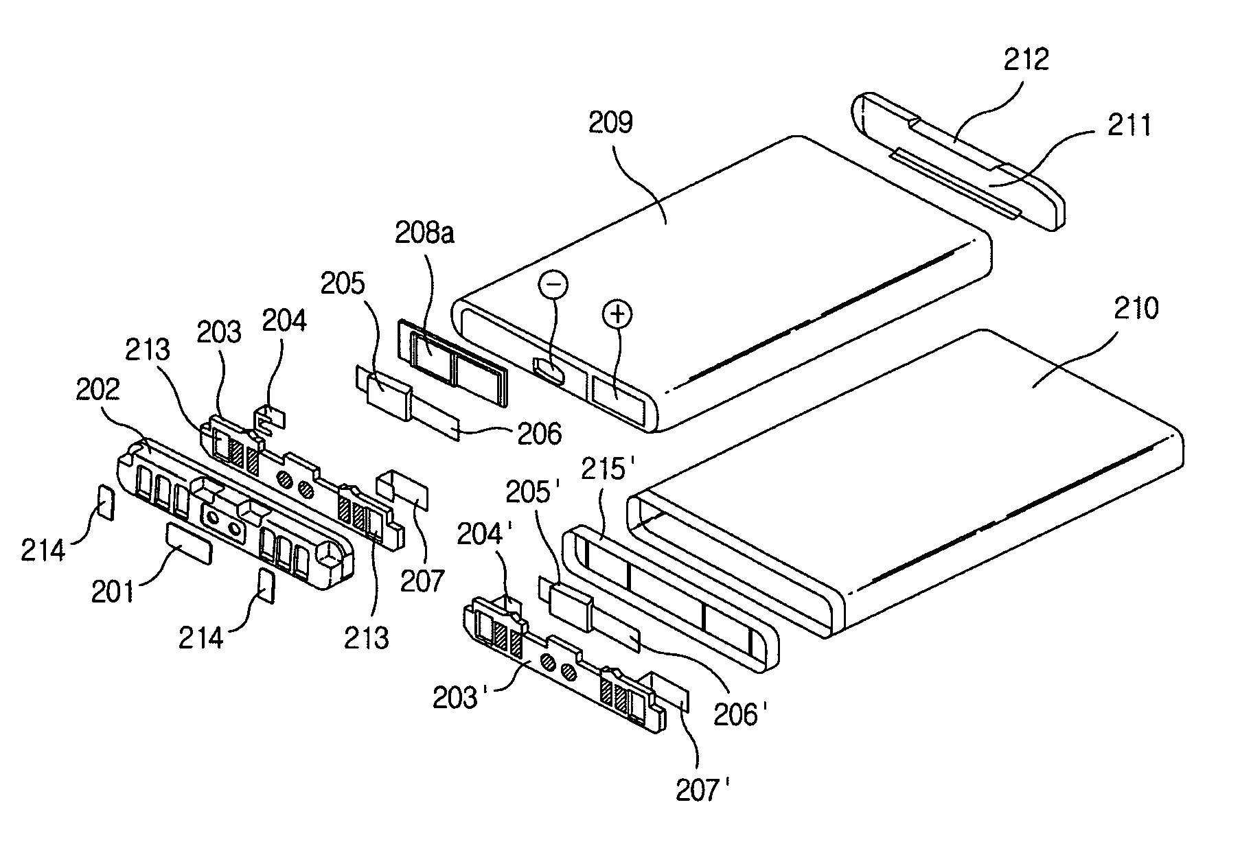
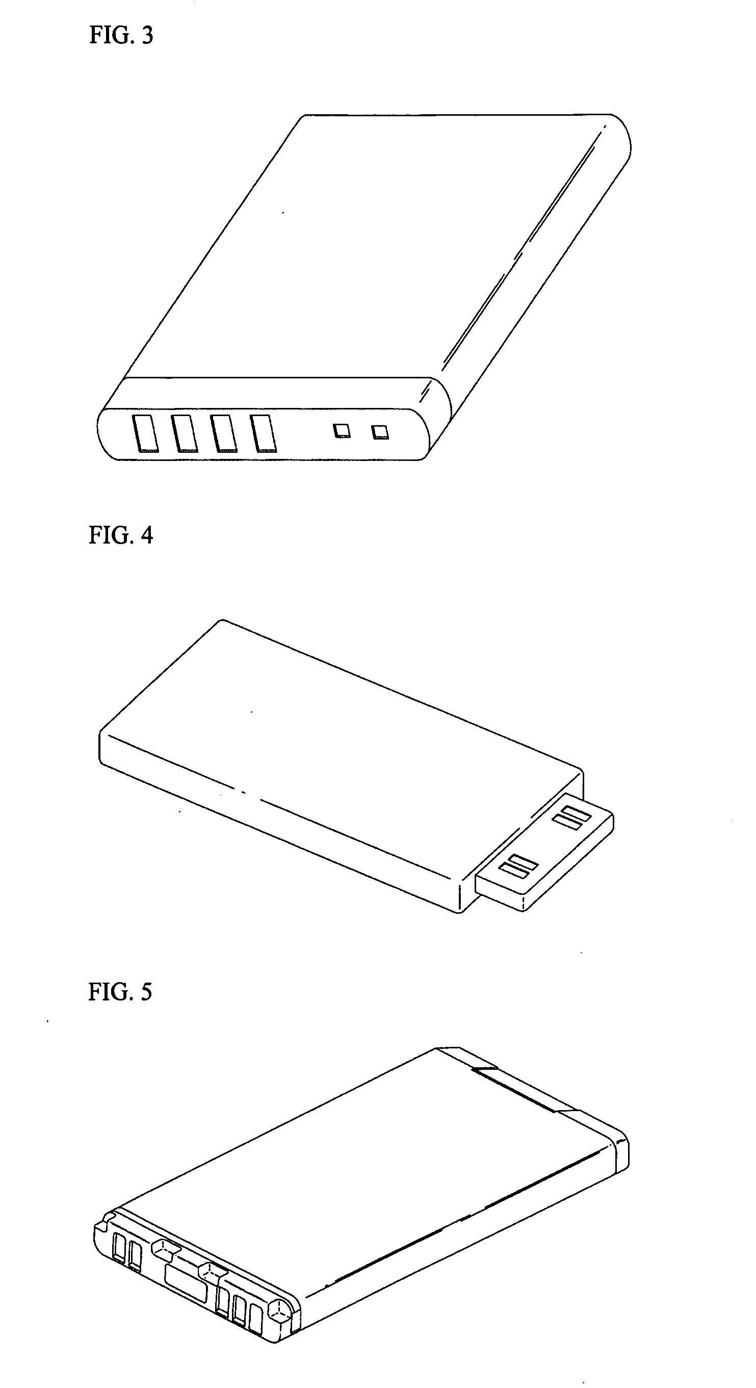
[0033]FIGS. 5 and 6 are perspective views of a label type battery pack according to the invention, in which FIG. 5 shows the internal battery pack having one connecting hole 213, and FIG. 6 shows the internal battery pack having two connecting holes 213.

[0034] The label type battery pack according to the first embodiment of the invention is constructed by injection molding a PCM assembly 203, and then joining the PCM assembly 203 to a battery cell A using a nickel plate 206 by means of spot welding. Since the battery cell is not formed by means of injection molding, the label type battery pack of the first embodiment has an advantage of ensuring a reliability of the battery cell A. More detailed construction thereof will be described below with reference to FIGS. 16 and 17.

second embodiment

[0035] FIGS. 7 to 9 are perspective views of a modified battery cell type battery pack according to the invention. FIGS. 7 and 8 show the modified cell type battery pack using lockers 216 and locker grooves 217, in which FIG. 7 shows the battery pack having one connecting hole 213, and FIG. 8 shows the battery pack having two connecting holes 213. FIG. 9 shows the battery pack using a clamper 218.

[0036] The modified battery cell type battery pack according to the second embodiment of the invention comprises a battery cell A which is provided with an aluminum top can protruded a predetermined length from an upper surface of the battery cell A having cathode and anode terminals formed thereon, and a PCM block B which is inserted into the top can and is then fixed to the battery cell A by means of the lockers 216 and the locker grooves 217 or the clamper 218. More detailed construction thereof will be described below with reference to FIGS. 18 and 19.

third embodiment

[0037]FIGS. 10 and 11 are perspective views of a case insertion type battery pack according to the invention, in which FIG. 10 shows the internal battery pack having one connecting hole 213, and FIG. 11 shows the internal battery pack having two connecting holes 213.

[0038] The case insertion type battery pack according to the third embodiment of the invention is constructed such that after attaching a PCM block B having an injection molded PCM assembly 203 to a battery cell A, the PCM block B attached to the battery cell A is inserted into a case 400 so as to penetrate the case 400, and is then fixed by lockers 216. More detailed construction thereof will be described below with reference to FIGS. 20 and 21.

[0039] FIGS. 12 to 15 are bottom views of the PCM block according to a position of the connecting hole of the invention, showing a case where the connecting hole 213 is located at the right on the PCM block, a case where the connecting hole 213 is located at the left on the PCM ...


PUM

PropertyMeasurementUnit
electricalaaaaaaaaaa
rated operating voltageaaaaaaaaaa
sizeaaaaaaaaaa

Abstract

A battery pack comprising a battery cell having electrode terminals formed on an upper surface of the battery cell, and a protective circuit module (PCM) block mounted on the battery cell, wherein one or more connecting holes for electrical connection between the battery cell and the PCM block are perforated through the PCM block such that a connecting portion between the battery cell and the PCM block is exposed to the outside of the upper surface of the battery cell. The battery pack is lighter, compacter and miniaturized, thereby allowing an electronic device employing the battery pack to be reduced in an overall size, enhancing workability through a simplified assembling process, reducing manufacturing costs through reduction of the number of components, and enhancing productivity through reduction of the number of operating steps by eliminating additional installation steps.

Description

FIELD OF THE INVENTION [0001] The present invention relates to a battery pack having an improved structure, and, more particularly, to a battery pack, which comprises a battery cell having electrode terminals formed on an upper surface thereof, and a protective circuit module (PCM) block mounted on the battery cell, in which at least one connecting hole for electrically connecting the battery cell and the PCM block is perforated through the PCM block such that a joined portion of the battery cell and the PCM block is exposed to the outside of the upper surface. BACKGROUND OF THE INVENTION [0002] A rechargeable secondary battery is generally classified into hard pack batteries and internal batteries. FIG. 1 shows an exploded perspective view of a mobile telecommunication terminal with a conventional internal battery separated from the terminal. [0003] Referring to FIG. 1, the mobile telecommunication terminal with the conventional internal battery comprises a body 100, a battery rece...

Claims


Application Information

Patent Timeline
Patent Type & Authority Applications(United States)
IPC IPC(8): H01M10/00H01M10/40H01M10/42H01M50/55H01M50/553H01M50/562H01M50/566H01M50/572
CPCH01M2/30H01M10/425H01M10/0525H01M2/34Y02E60/10H01M50/572H01M50/553H01M50/562H01M50/55H01M50/566H01M50/20
Inventor MOON, KI EOBJUNG, CHUN KILKOOK, YOON SANGSUK, DONG YOUL
Owner LG ENERGY SOLUTION LTD
Why Eureka
Try Eureka