Secondary battery

a battery and secondary technology, applied in the field of secondary batteries, can solve the problems of individual battery cells suffering to have their volume dispersed to a certain extent, battery cells having small volumes tend to be rather overdischarged, so as to achieve secure safety and design exaltation, the effect of simple structur

Inactive Publication Date: 2005-09-22
NISSAN MOTOR CO LTD
View PDF5 Cites 10 Cited by
  • Summary
  • Abstract
  • Description
  • Claims
  • Application Information

AI Technical Summary

Benefits of technology

[0008] This invention has originated in the light of such problems of the prior art as mentioned above and is aimed at providing a secondary battery which, by having a group of diodes connected between a positive pole and a negative pole of a secondary batter, is enabled to secure safety and design exaltation of the service life of a battery with a simple structure.

Problems solved by technology

Since the positive poles, the negative poles, and the nonaqueous electrolyte layers nevertheless cannot be formed equally in thickness and surface area, however, the individual battery cells are suffered to have their volumes dispersed to a certain extent.
When the battery cells have their volumes dispersed, those of smaller volumes are first charged fully to capacity during the course of charging and those of such small volumes tend to be rather overcharged.
Meanwhile, during the course of discharging, the battery cells of smaller volumes first complete discharging, the battery cells having small volumes tend to be rather overdischarged.
Incidentally, when the techniques disclosed in these patent documents are applied to the secondary battery, they possibly result in varying the impedance of the secondary battery as a whole and degrading the performance of the secondary battery under the influence of the separated battery cells and they also necessitate a complicated control circuit for keeping a constant watch on the voltages of the individual battery cells and effecting a control for separating or blocking the battery cells which have developed abnormal voltages.

Method used


Image

  • Secondary battery
  • Secondary battery
  • Secondary battery

Examples


example 1

[0086] A group of diodes was manufactured by connecting in series five 6A Diodes made by General Semiconductor Corp. When a voltage was applied gradually to the group of diodes and the electric current flowing out of them was measured, results similar to those shown in FIG. 6 were obtained. Next, a 20-unit module battery was manufactured by preparing 20 such groups of diodes, connecting 20 separately prepared canned 1600 mAh lithium ion batteries (4.2 V during ordinary charging and 2.5V during discharging) one each in the forward direction to the 20 groups of diodes, and thereafter connecting the individual batteries in series. This module battery was not furnished particularly with a protective circuit. Further, 20 such module batteries were prepared and subjected to charging and discharging at 3200 mA and 50 V of lower limit and 80 V of upper limit respectively of cutoff voltage up to 100 repetitions. Thereafter, the module batteries were examined to find any sign of abnormality a...

example 2

[0088] To each of the module batteries of Example 1, one 6A diode produced by General Semiconductor Corp was connected in the reverse direction. Twenty (20) such module batteries were prepared and were subjected to charging and discharging at 3200 mA and 50 V of lower limit and 80 V of upper limit respectively of cutoff voltage up to 100 repetitions. Thereafter, the module batteries were examined to find any sign of abnormality and tested for 1 C discharge capacity from 72 V.

[0089] As a result, none of the 20 module batteries was found to have induced any leakage and none of them was found to emit smoke. The module batteries had a capacity (average) of 748 mAh prior to the cycles and a capacity (average) of 681 mAh after the cycles. The ratio of the charging capacity to the discharging capacity in the final cycle was 95%.

example 3

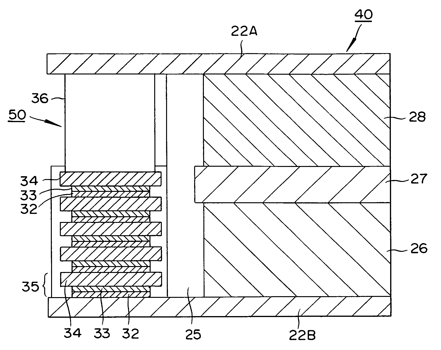
[0093] A SUS 316 stainless steel sheet measuring 20 μm in thickness and 20 cm×30 cm in surface area was prepared. A coating material produced by dissolving lithium manganese, LiMn2O4, having a diameter of 10 μm, acetylene black, and a PVDF binder at a composition of 90:5:5 in N-methyl pyrrolidone was applied to the central part, 18 cm×26 cm, on one side of this sheet, and dried to prepare a positive pole active substance layer 50 μm in thickness.

[0094] Next, a coating material produced by dissolving hard carbon having a diameter of 10 μm in diameter and a PVDF binder in a composition of 90:10 in N-methyl pyrrolidone was applied to the central part, 18 cm×26 cm, on the rear side of the sheet and dried to prepare a negative pole active substance layer 50 μm in diameter.

[0095] At the positions 10 mm from the opposite edges of the short side, 20 cm, on the positive electrode active substance layer side of the stainless steel sheet, silver, p-dope silicon, and n-dope silicon were each ...


PUM

PropertyMeasurementUnit
thicknessaaaaaaaaaa
thicknessaaaaaaaaaa
voltageaaaaaaaaaa

Abstract

This invention concerns a secondary battery which ensures safety with a simple structure and promotes exaltation of the service life of battery. This secondary battery is formed by interposing a nonaqueous electrolyte between the positive pole and the negative pole and connecting a group of diodes between the positive pole terminal forming the positive pole and the negative pole terminal forming the negative pole in the direction in which the forward direction voltage is applied. Owing to this structure, the secondary battery is enabled to possess the function of protecting the battery from overcharging and overdischarging even when the voltage is abnormally lowered during the course of discharging.

Description

BACKGROUND OF THE INVENTION [0001] 1. Field of the Invention [0002] This invention relates to a secondary battery which possesses the function of protecting itself from overcharging or overdischarging even when the voltage abnormally rises during the course of charging or when the voltage abnormally falls during the course of discharging. [0003] 2. Description of Related Art [0004] In recent years, the hybrid electric vehicle (HEV) has begun undergoing reduction into practical use in response to the mounting public consciousness of the environmental problem. The secondary battery is used as the power source for the motor which is mounted on the HEV. In answer to the demand for decreasing size and weight, the thin battery of a high energy density has come to find popular acceptance. The thin battery is formed by laminating a plurality of battery cells each resulting from interposing a nonaqueous electrolyte between positive poles and negative poles each of the shape of a sheet. [0005...

Claims


Application Information

Patent Timeline
Patent Type & Authority Applications(United States)
IPC IPC(8): H01M4/64H01M2/34H01M10/04H01M10/05H01M10/058H01M10/42H01M10/44H01M10/48H02H7/18
CPCH01M10/0418H01M10/0525Y02T10/7011H01M10/4257H01M10/441H01M10/4207Y02E60/10Y02P70/50
Inventor NAGAYAMA, MORINEMOTO, KOUICHI
Owner NISSAN MOTOR CO LTD
Why Eureka
Try Eureka