Intracutaneous microneedle array apparatus

a microneedle array and apparatus technology, applied in the field of medical devices, can solve the problems of small fraction of topically applied drugs entering the skin, poor efficiency, skin irritation, etc., and achieve the effects of facilitating biological fluid sampling, less expensive, and reducing the number of microneedle arrays

Inactive Publication Date: 2005-09-22
CORIUM INC
View PDF99 Cites 316 Cited by
  • Summary
  • Abstract
  • Description
  • Claims
  • Application Information

AI Technical Summary

Benefits of technology

[0014] Accordingly, it is a primary advantage of the present invention to provide a microneedle array in the form of a patch which can perform intracutaneous drug delivery. It is another advantage of the present invention to provide a microneedle array in the form of a patch that can perform biological body-fluid testing and / or sampling (including interstitial fluids and / or blood). It is a further advantage of the present invention to provide a microneedle array as part of a closed-loop system to control drug delivery, based on feedback information that analyzes body fluids, which can achieve real time continuous dosing and monitoring of body activity. It is yet another advantage of the present invention to provide an electrophoretically / microneedle-enhanced transdermal drug delivery system in order to achieve high-rate drug delivery and to achieve sampling of body fluids. It is a yet further advantage of the present invention to provide a method for manufacturing an array of microneedles using microfabrication techniques, including standard semiconductor fabrication techniques. It is still another advantage of the present invention to provide a method of manufacturing an array of microneedles comprising a plastic material by a “self-molding” method, a micromolding method, a microembossing method, or a microinjection method. It is still another advantage of the present invention to provide an array of edged microneedles that, in one configuration are hollow and have at least one blade with a substantially sharp edge that assists in penetration of the stratum corneum of skin, and in another configuration the microneedles are solid and have at least one blade with a substantially sharp edge to assist in penetrating the stratum corneum. It is still a further advantage of the present invention to provide a microneedle array that has sufficient separation distance between the individual microneedles so as to ensure penetration of the stratum corneum of skin to achieve greater transdermal flux. It is still another advantage of the present invention to provide a method of manufacturing an array of microneedles in which a metal mold is initially manufactured for use in a microembossing procedure, while allowing a sufficient separation distance between individual microneedles of the array, then use a procedure for creating hollow chambers and through-holes in the substrate of the microneedle array. It is yet another advantage of the present invention to provide a microneedle array that has sensing capabilities using optical, spectroscopic, calorimetric, electrochemical, thermal, gravimetric, and light scattering sensing means. It is still another advantage of the present invention to provide a method for manufacturing an array of microneedles that uses shear forces during a de-molding procedure to create sharp hollow microneedles.
[0015] Additional advantages and other novel features of the invention will be set forth in part in the description that follows and in part will become apparent to those skilled in the art upon examination of the following or may be learned with the practice of the invention.
[0016] To achieve the foregoing and other advantages, and in accordance with one aspect of the present invention, a first embodiment of an improved microneedle array is constructed of silicon and silicon dioxide compounds using MEMS (i.e., Micro-Electro-Mechanical-Systems) technology and standard microfabrication techniques. The microneedle array may be fabricated from a silicon die which can be etched in a microfabrication process to create hollow or solid individual microneedles. The resulting array of microneedles can penetrate with a small pressure through the stratum corneum of skin (including skin of animals, reptiles, or other creatures—typically skin of a living organism) to either deliver drugs or to facilitate biological fluid sampling (e.g., sampling interstitial fluids and / or blood) through the hollow microneedles or pores made through skin via solid microneedles. The drug reservoir, and / or the chemical analysis components for sampling body fluid, may be fabricated inside the silicon die, or an additional thick film layer can be bonded or otherwise attached over the silicon substrate to create the reservoir. The delivery of drugs and sampling of fluids can be performed by way of passive diffusion (e.g., time release), instantaneous injection, pressure, vacuum, ultrasound, or electrophoresis (e.g., iontophoresis). A complete closed-loop system can be manufactured including active elements, such as micro-machined pumps, heaters, and mixers, as well as passive elements such as sensors. A “smart patch” can thereby be fabricated that samples body fluids, performs chemistry to decide on the appropriate drug dosage, and then administers the corresponding amount of drug. Such a system can be made disposable, including one with an on-board power supply.
[0017] In a second embodiment, an array of hollow (or solid) microneedles can be constructed of plastic or some other type of molded or cast material. When using plastic, a micro-machining technique is used to fabricate the molds for a plastic microforming process. The molds are detachable and can be re-used. Since this procedure requires only a one-time investment in the mold micro-machining, the resulting plastic microstructure should be much less expensive than the use of microfabrication techniques to construct microneedle arrays, as well as being able to manufacture plastic microneedle arrays much more quickly and accurately. It will be understood that such hollow microneedles may also be referred to herein as “hollow elements,” or “hollow projections,” including in the claims. It will also be understood that such solid microneedles may also be referred to herein as “solid elements,” or “solid projections” (or merely “projections”), including in the claims.
[0018] Molds used in the second embodiment of the present invention can contain a micropillar array and microhole array (or both), which are fabricated by micro-machining methods. Such micro-machining methods may include micro electrode-discharge machining to make the molds from a variety of metals, including stainless steel, aluminum, copper, iron, tungsten, and their alloys. The molds alternatively can be fabricated by microfabrication techniques, including deep reactive etching to make silicon, silicon dioxide, and silicon carbide molds. Also, LIGA or deep UV processes can be used to make molds and / or electroplated metal molds.
[0019] The manufacturing procedures for creating plastic (or other moldable material) arrays of microneedles include: “self-molding,” micromolding, microembossing, and microinjection techniques. In the “self-molding” method, a plastic film (such as a polymer) is placed on a micropillar array, the plastic is then heated, and plastic deformation due to gravitational force causes the plastic film to deform and create the microneedle structure. Using this procedure, only a single mold-half is required. When using the micromolding technique, a similar micropillar array is used along with a second mold-half, which is then closed over the plastic film to form the microneedle structure. The micro-embossing method uses a single mold-half that contains an array of micropillars and conical cut-outs (microholes) which is pressed against a flat surface (which essentially acts as the second mold-half) upon which the plastic film is initially placed. In the microinjection method, a melted plastic substance is injected between two micro-machined molds that contain microhole and micropillar arrays.

Problems solved by technology

The main challenge in transcutaneous drug delivery is providing sufficient drug penetration across the skin.
Current topical drug delivery methods are based upon the use of penetration enhancing methods, which often cause skin irritation, and the use of occlusive patches that hydrate the stratum corneum to reduce its barrier properties.
Only small fractions of topically applied drug penetrates through skin, with very poor efficiency.
Convention methods of biological fluid sampling and non-oral drug delivery are normally invasive.
That is, the skin is lanced in order to extract blood and measure various components when performing fluid sampling, or a drug delivery procedure is normally performed by injection, which causes pain and requires special medical training.
In this Georgia Tech design, however, the fluid is prone to leakage around the array of microneedles, since the fluid is on the exterior surface of the structure holding the microneedles.

Method used


Image

  • Intracutaneous microneedle array apparatus
  • Intracutaneous microneedle array apparatus
  • Intracutaneous microneedle array apparatus

Examples


second embodiment

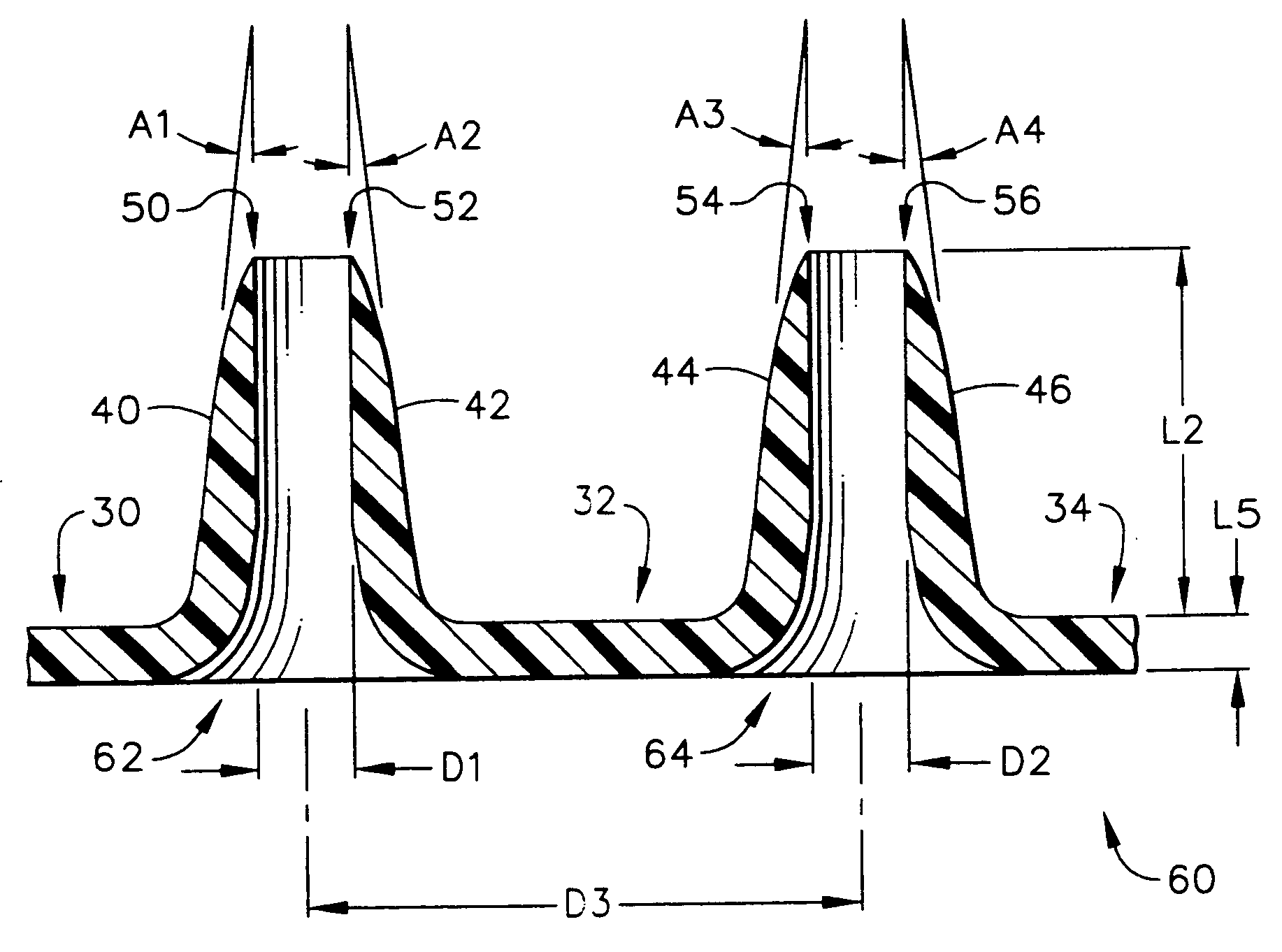
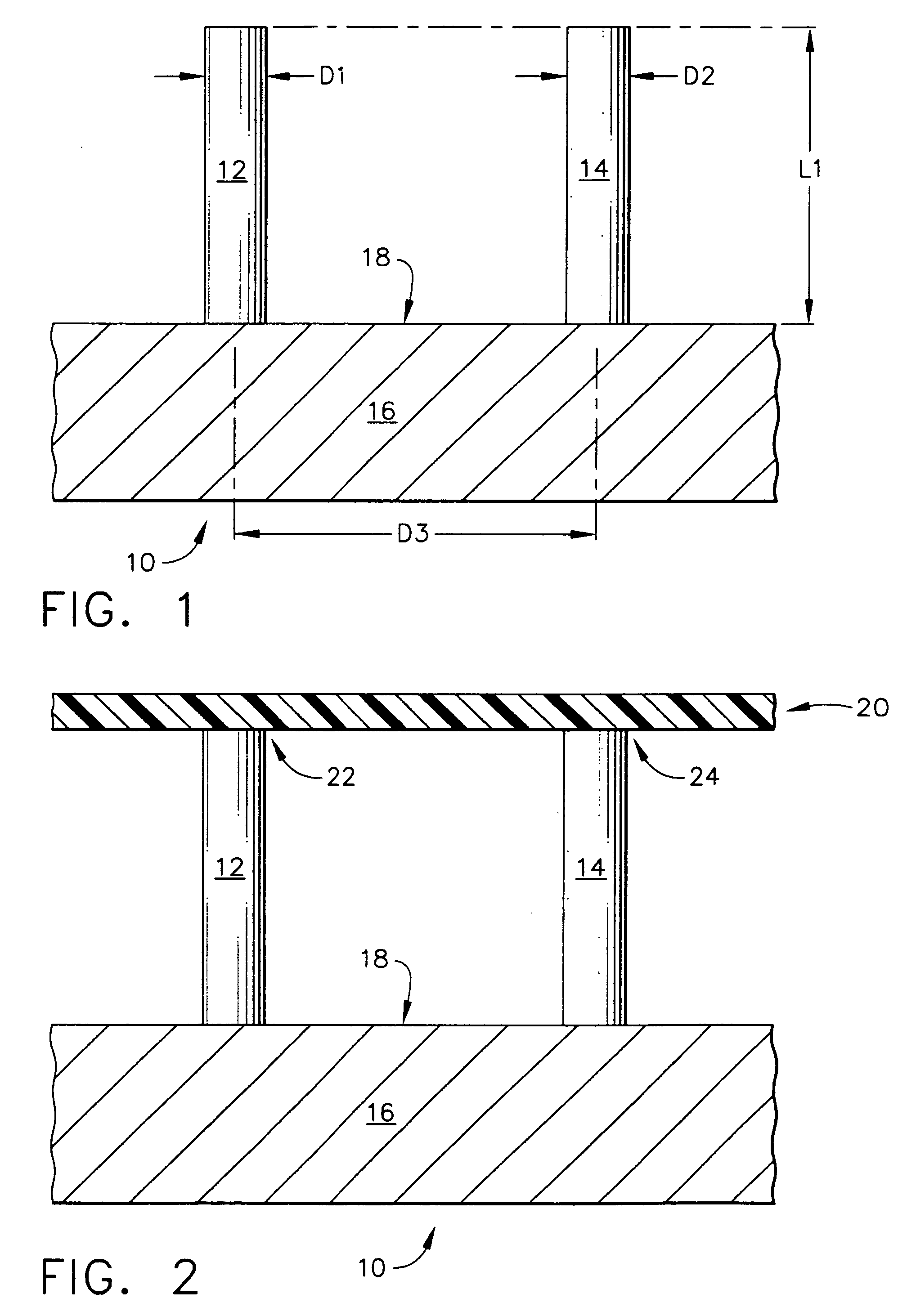
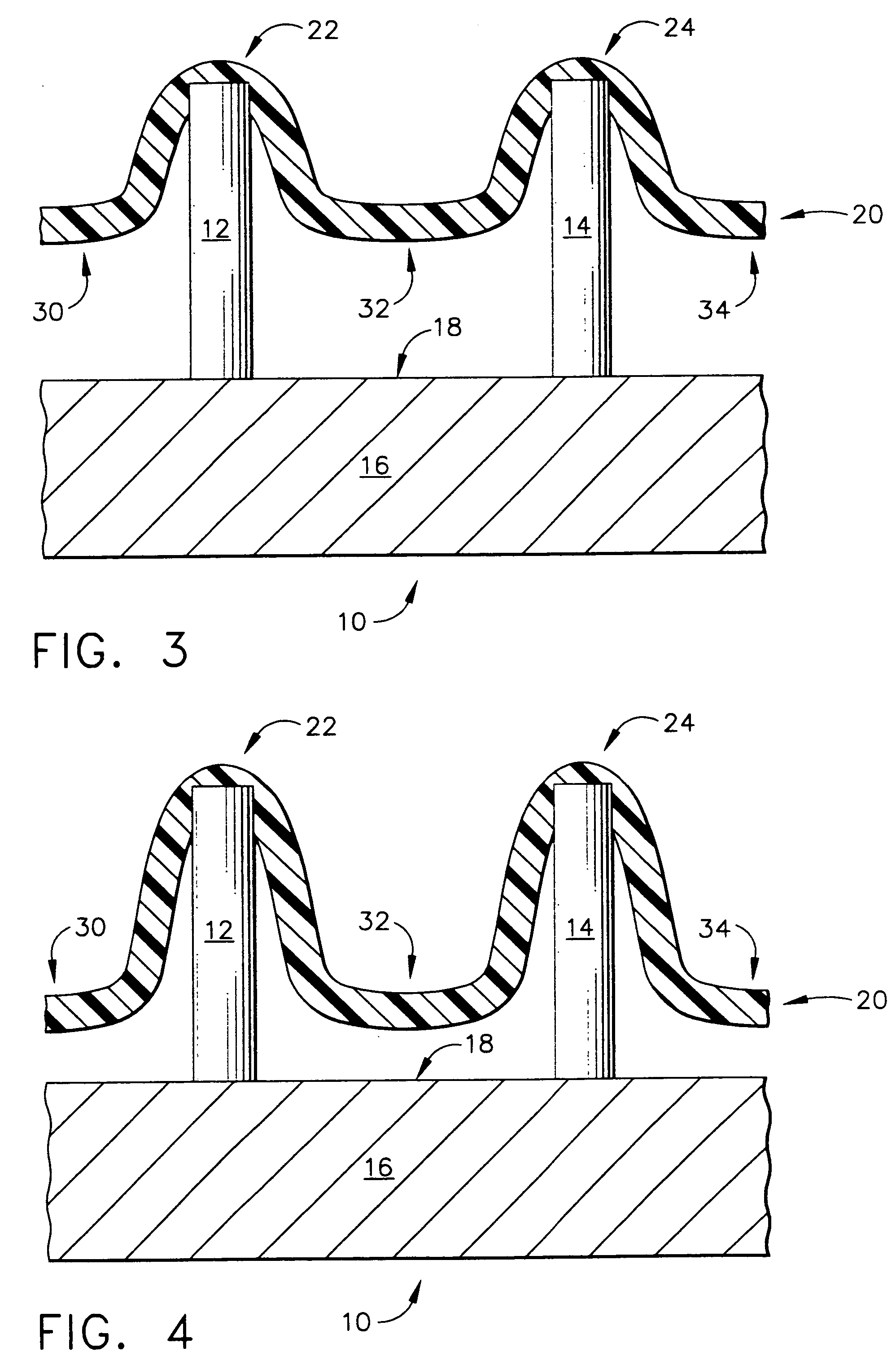
[0103]FIG. 7 depicts a top mold-half, generally designated by the reference numeral 110, of the present invention in which the manufacturing method for creating an array of hollow microneedles is performed by a micromolding procedure. The top mold-half 110 includes two “microholes” that have sloped side walls, designated by the reference numerals 112 and 114 for the left-hand microhole 113, and by the reference numerals 116 and 118 for the right-hand microhole 117. The microholes 113 and 117 have a vertical (in FIG. 7) dimension referred to herein as a distance “L11”. Microholes 113 and 117 correspond to a pair of micropillars 122 and 124 that are part of a bottom mold-half, generally designated by the reference number 120, and illustrated in FIG. 8.

[0104] Referring back to FIG. 7, the sloped side walls of the microhole 113 are depicted by the angles “A11” and “A12,” with respect to the vertical. The side walls of microhole 117 are also sloped with respect to the vertical, as illust...

embodiment 550

[0161] An alternative embodiment 550 is depicted in FIG. 24, in which the microneedles 580 are solid, rather than hollow. A fluid-filled chamber 560 is provided and also comprises hydrogel filled with glucose oxidase. The chamber 560 is made of a bottom wall 562 that has openings proximal to the individual microneedles 580, in which these openings are designated by the reference numeral 585. Chamber 560 also includes side walls 564 and 566, as well as electrodes 570, 572, and 575.

[0162] The electrode 575 is constructed as part of the bioelectrochemical sensor. The electrodes 570 and 572 act as the electrophoretic electrodes, acting either as an anode or cathode to set up an electric current through the skin which flows to a remotely-attached (to the skin) electrode (e.g., electrode assembly 555, viewed on FIG. 26).

[0163] As in the sensor 500 of FIG. 23, the transport rate of fluids is enhanced by not only the piercing effect of the microneedles 580, but also the electric field indu...

embodiment 555

[0169] An alternative embodiment 555 is depicted in FIG. 26, in which the microneedles 581 are solid, rather than hollow. A fluid chamber 561 is provided and preferably is filled with hydrogel (which is not electrically charged). Chamber 561 is made of a bottom wall 563 that has openings proximal to the individual microneedles 581, in which these openings are designated by the reference numeral 586. Chamber 561 also includes side walls 565 and 567, as well as a top (or ceiling) electrode 576. The electrode 576 may act as a cathode, for example, in a situation where electrode assembly 555 is being used in conjunction with a body-fluid sensor, such as sensor assembly 550 viewed on FIG. 24, in which its electrodes 570 and 572 may act, for example, as an anode. The height “L57” of fluid chamber 561 could be any reasonable dimension that is large enough to hold a sufficient volume of the hydrogel to enhance the fluid flow via the electric field between the respective anode and cathode of...


PUM


Abstract

Improved microneedle arrays are provided having a sufficiently large separation distance between each of the individual microneedles to ensure penetration of the skin while having a sufficiently small separation distance to provide high transdermal transport rates. A very useful range of separation distances between microneedles is in the range of 100-300 microns, and more preferably in the range of 100-200 microns. The outer diameter and microneedle length is also very important, and in combination with the separation distance will be crucial as to whether or not the microneedles will actually penetrate the stratum corneum of skin. For circular microneedles, a useful outer diameter range is from 20-100 microns, and more preferably in the range of 20-50 microns. For circular microneedles that do not have sharp edges, a useful length for use with interstitial fluids is in the range of 50-200 microns, and more preferably in the range of 100-150 microns; for use with other biological fluids, a useful length is in the range of 200 microns—3 mm, and more preferably in the range of 200-400 microns. For circular microneedles having sharp side edges, a useful length for use with interstitial fluids is in the range of 50-200 microns, and more preferably in the range of 80-150 microns; for use with other biological fluids, a useful length is again in the range of 200 microns—3 mm, and more preferably in the range of 200-400 microns. For solid microneedles having a star-shaped profile with sharp edges for its star-shaped blades, a useful length for use with interstitial fluids is in the range of 50-200 microns, and more preferably in the range of 80-150 microns; for use with other biological fluids, a useful length is again in the range of 200 microns—3 mm, and more preferably in the range of 200-400 microns, while the radius of each of its blades is in the range of 10-50 microns, and more preferably in the range of 10-15 microns.

Description

CROSS REFERENCES TO RELATED APPLICATIONS [0001] This is a continuation-in-part of prior application Ser. No. 09 / 329,025 (P&G Case 7606), filed on Jun. 9, 1999.TECHNICAL FIELD [0002] The present invention relates generally to medical devices and is particularly directed to a fluid dispensing device and a fluid sampling device of the type which, in one embodiment penetrates the stratum corneum and epidermis, but not into the dermis of skin, and in another embodiment penetrates into the dermis so as to interface with blood or other biological fluids. The invention is specifically disclosed as an array of microneedles which painlessly and with minimal trauma to the skin enable fluid transfer either into a body as a dispensing device, or from the body to sample body fluid. BACKGROUND OF THE INVENTION [0003] Topical delivery of drugs is a very useful method for achieving systemic or localized pharmacological effects. The main challenge in transcutaneous drug delivery is providing sufficie...

Claims


Application Information

Patent Timeline
Patent Type & Authority Applications(United States)
IPC IPC(8): A61M5/00A61M5/172A61M37/00A61N1/30
CPCA61M5/1723A61M37/0015A61M2037/0023A61M2037/003B81C99/0085A61M2037/0061A61N1/30B81B2201/055A61M2037/0053
Inventor YUZHAKOV, VADIM VLADIMIROVICHSHERMAN, FAIZ FEISALOWENS, GROVER DAVIDGARTSTEIN, VLADIMIR
Owner CORIUM INC
Why Eureka
Try Eureka