
Infinitely variable, order specific, holistic assembly process control system

Inactive Publication Date: 2005-09-22
DEERE & CO
View PDF8 Cites 2 Cited by
  • Summary
  • Abstract
  • Description
  • Claims
  • Application Information

AI Technical Summary

Benefits of technology

[0007] To be successful in the creation of an effective yet holistic mistake-proofing method that is flexible enough to be utilized for all manner of production situations and product variability encountered in manufacturing, it is necessary to integrate source data to minimize the error risk of data duplication. It is thus necessary to design a solution to utilize any and all configurations to minimize maintenance. The creation of standardized approaches can greatly simplify the complexity and drive implementation savings through the economy of scale. The human interface needs to utilize technology to allow for a system to automate and eliminate the interaction of the individual required in as many ways as possible. The method needs to provide for closed loop processes, and the notification of errors in clear, concise recognizable language when errors do occur. The system for monitoring assembly processes needs to be an open architecture design to accommodate any currently available sensing device and also future devices not yet available. The assembly process mistake-proofing strategy needs to prevent further movement of the product along the assembly line until sensed errors are corrected, and if not correctable, reported, so product disposition can be resolved.
[0010] A further object of the invention is to provide an integrated assembly process monitoring and mistake-proofing system that is holistic and infinitely variable.

Problems solved by technology

Such operations are subject to a number of opportunities for error i.e. omission of required parts, use of the wrong assembly tool, use of the wrong part in a particular location, incorrect torque, etc.
These problems are only compounded in facilities where numerous models or variations of parts are assembled on the same line.
Such errors or defects, if left undiscovered result in recalls, rejections by customers or returns or warranty claims by end users, all causing a great deal of expense for the manufacturer, distributor and dealer, and a general dissatisfaction among end users.
Accordingly, an unacceptable percentage of products are passed down the line without all assembly steps having been completed.
However, in the assembly process the human factor is difficult to include in a mistake-proofing system.
Numerous tools and techniques have been developed to aid in controlling the assembly process, but attempts to date have only been capable of monitoring single product configurations or are so expensive and complicated to configure, deploy and sustain that they are virtually impractical.
These are limited to not allowing the display of the next instruction set and instructions are specific to each product.
This strategy is good, but in a manufacturing situation where an assembly line has significant variability in product configuration, it is not manageable.
While these approaches do much toward always knowing where a product is in the assembly process and that the components are available and accounted for, they do not go beyond this component matching, and tracking strategy to improve quality.
Without the mistake-proofing method described below, the number of methods, tools, and options for mistake-proofing are limited by a variety of typical assembly process complications that limit what methods can be used to solve individual process or part verification techniques.
Such things as product option configurations, mixed model production, and cycle time at a given assembly station make previous solutions impractical.

Method used


Image

  • Infinitely variable, order specific, holistic assembly process control system
  • Infinitely variable, order specific, holistic assembly process control system
  • Infinitely variable, order specific, holistic assembly process control system

Examples


Embodiment Construction

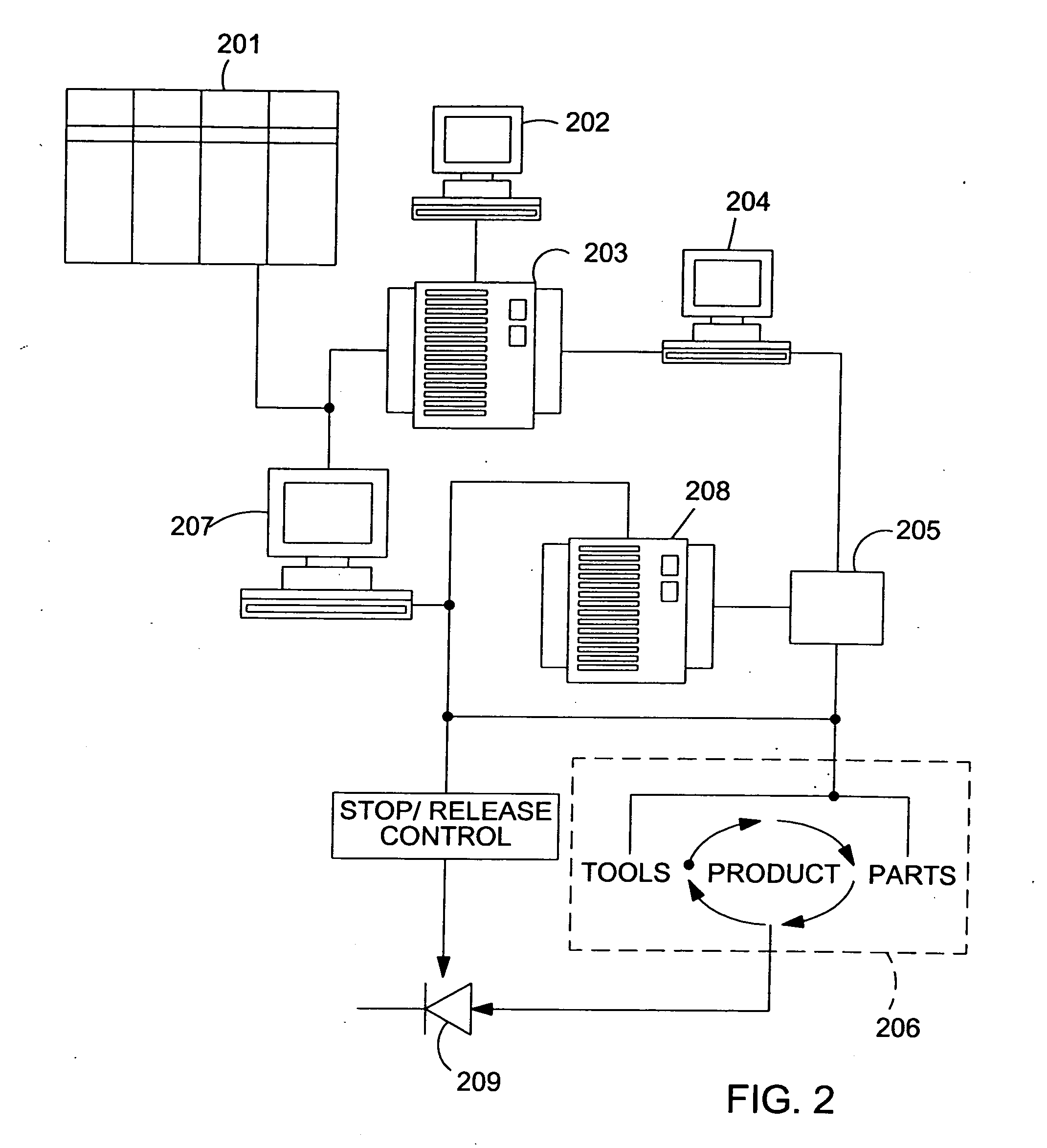
[0023] Referring first to FIG. 2 it will be seen that the invention of the present application is implemented using a networked data processing system. A mainframe server 201 is provided, containing all current product specifications including product bills of material (BOM), tooling, time standards and order configurations. Manufacturing engineering personnel enter data via a terminal at 202 into an operations data server at 203. This data includes assignment of assemblies to operations and defines part / bench locations. Action definitions (specific sensors or PLC action) are also entered, along with error messages to be displayed if an action fails. Actions are collected and assembled into action groups, which are in turn related to assemblies. Visual aids for assembly operations may be provided and related to specific assemblies. At 204 Systems Integration personnel create PLC logic, tag names, and program IDs based upon the definitions previously provided by manufacturing enginee...


PUM


Abstract

Interfaces are provided which integrate mistake-proofing concepts in a way easily understandable by the operator and easily configured by a manufacturing engineer. As mistake-proofing concepts are developed tables are populated and associated with specific assembly processes. Sensors are employed to monitor parts selection and tool usage. Sensors used for tool use and parts selection, error messages and actions to be performed or monitored are all defined and related in the tables and in turn to specific assembly orders. The tables are also populated with logic pointers, which are referenced by a Process Logic Control (PLC) unit that has been programmed to recall and carry out infinitely variable monitoring or control of the assembly process. For example when a particular order has been identified to the PLC by way of a scanned barcode or other means, a bill of material and assembly sequence is provided to the operator by appropriate means such as a CRT monitor. Parts bins and assembly points may be indicated by visual or other means to indicate parts and tools to be used and assembly points. Sensors determine when the proper part has been selected for the particular assembly step and / or whether the appropriate tool is used. The PLC then provides feedback to the operator to indicate whether all necessary steps have been accomplished in the proper order, with the proper parts using the proper tools. The PLC will provide the operator with understandable error messages indicating when a step has been improperly completed. The PLC can also control stops on the line to prevent the assembly from moving forward until all steps have been completed according to the specific order program. An override means may also be provided to bypass the PLC controls in which case an error log is compiled and an automated message is sent to supervisory personnel indicating that the system was overridden by the operator and follow up action is required.

Description

CROSS-REFERENCE TO RELATED APPLICATION [0001] This application is a division of applicant's co-pending application U.S. Ser. No. 10 / 767,799, filed 29 Jan. 2004 and titled INFINITELY VARIABLE, ORDER SPECIFIC, HOLISTIC ASSEMBLY PROCESS CONTROL SYSTEM, which application is pending. [0002] This application claims priority under 35 USC § 119(e) from U.S. Provisional Application 60 / 444,416 filed Feb. 3, 2003 under 35 USC § 111(b).FIELD OF THE INVENTION [0003] The present invention relates generally to computer implemented manufacturing systems. More particularly, the present invention relates to computer integrated manufacturing workstations wherein production and assembly of parts are monitored. Specifically, the present invention relates to an infinitely variable, order specific, mistake-proofing system for ensuring quality in a production or assembly environment. BACKGROUND OF THE INVENTION [0004] While the use of automated production and assembly systems in product manufacturing is we...

Claims


Application Information

Patent Timeline
IPC IPC(8): G05B19/418G06F11/30G06F19/00
CPCG05B19/41805G05B19/4184G05B2219/36371G05B2219/31455G05B2219/31461G05B2219/31059Y02P90/02
Inventor HOPPES, VERN RICHARDKRIENER, LARRY LINNPIPHO, MATTHEW JONEDGIN, JOSHUA MARKMITCHELL, JAMES ANTHONYSHEHATA, IBRAHIM HUSSEINRATH, ANTHONY NATEMILLS, ROBERT JOSEPHOSBORN, MICHAEL EUGENESMITH, MARK DOUGLASPHILLIPS, TERRY JOHNBORTOLAZZO, KEVIN DEANSINK, DAVE ANTHONYMYERS, JOEL FLOYDKRESSER, KENNETH JOHNMINER, GARY LEEMCNAUGHT, LESLEY ANN
Owner DEERE & CO
Features
  • Generate Ideas
  • Intellectual Property
  • Life Sciences
  • Materials
  • Tech Scout
  • Unparalleled Data Quality
  • Higher Quality Content
  • 60% Fewer Hallucinations
Learn More