Cooling system for a commercial aircraft galley

a cooling system and commercial aircraft technology, applied in the field of commercial aircraft galley cooling systems, can solve the problems of high condenser inlet temperature, higher failure rate and premature wear, and significantly heavier air chiller units, which would be inacceptable for us

Active Publication Date: 2005-09-29
BE INTPROP
View PDF11 Cites 118 Cited by
  • Summary
  • Abstract
  • Description
  • Claims
  • Application Information

AI Technical Summary

Benefits of technology

[0019] In a second embodiment, the invention provides for a cooling system for use on aircraft, including one or more galley cooling units having a galley plenum and an evaporator within the galley plenum for conveying heat from the galley plenum to an intermediate working fluid, and one or more liquid condensing chiller subsystems remotely located with respect to the at least one galley cooling unit. The one or more liquid condensing chiller subsystems include one or more recirculation units receiving the intermediate working fluid from the evaporator to cool the intermediate working fluid, and the one or more recirculation units include a compressor connected in fluid communication with the evaporator for receiving the intermediate working fluid from the evaporator for compressing the intermediate working fluid, and a liquid cooled condenser connected in fluid communication with the compressor for receiving compressed intermediate working fluid from the compressor for cooling the intermediate working fluid, the liquid cooled condenser connected in fluid communication with the evaporator for returning the intermediate working fluid to the evaporator. The one or more liquid condensing chiller subsystems also include at one or more heat expelling heat exchangers connected in fluid communication with the liquid cooled condenser for receiving a liquid coolant from the liquid cooled condenser for cooling the chiller liquid and recirculating the liquid coolant to the liquid cooled condenser.
[0020] In one aspect, the galley plenum includes ducts in communication with the evaporator to direct a flow of air in thermal communication with the evaporator through the galley plenum for cooling the galley plenum, and the galley plenum may include a galley blower for directing the flow of air through the galley plenum. In another aspect, the liquid cooled condenser may be connected in fluid communication with the compress

Problems solved by technology

In addition, when the air chillers are not mounted within the cabin of an aircraft, the air chillers commonly do not provide adequate condenser airflow and cooling efficiency when the aircraft are on the ground in hot ambient temperatures, producing high condenser inlet temperatures.
Furthermore, high operating temperatures that can occur under such conditions typically lead to higher failure rates and premature wear.
While one solution to the problem of providing adequate cooling

Method used


Image

  • Cooling system for a commercial aircraft galley
  • Cooling system for a commercial aircraft galley
  • Cooling system for a commercial aircraft galley

Examples


first embodiment

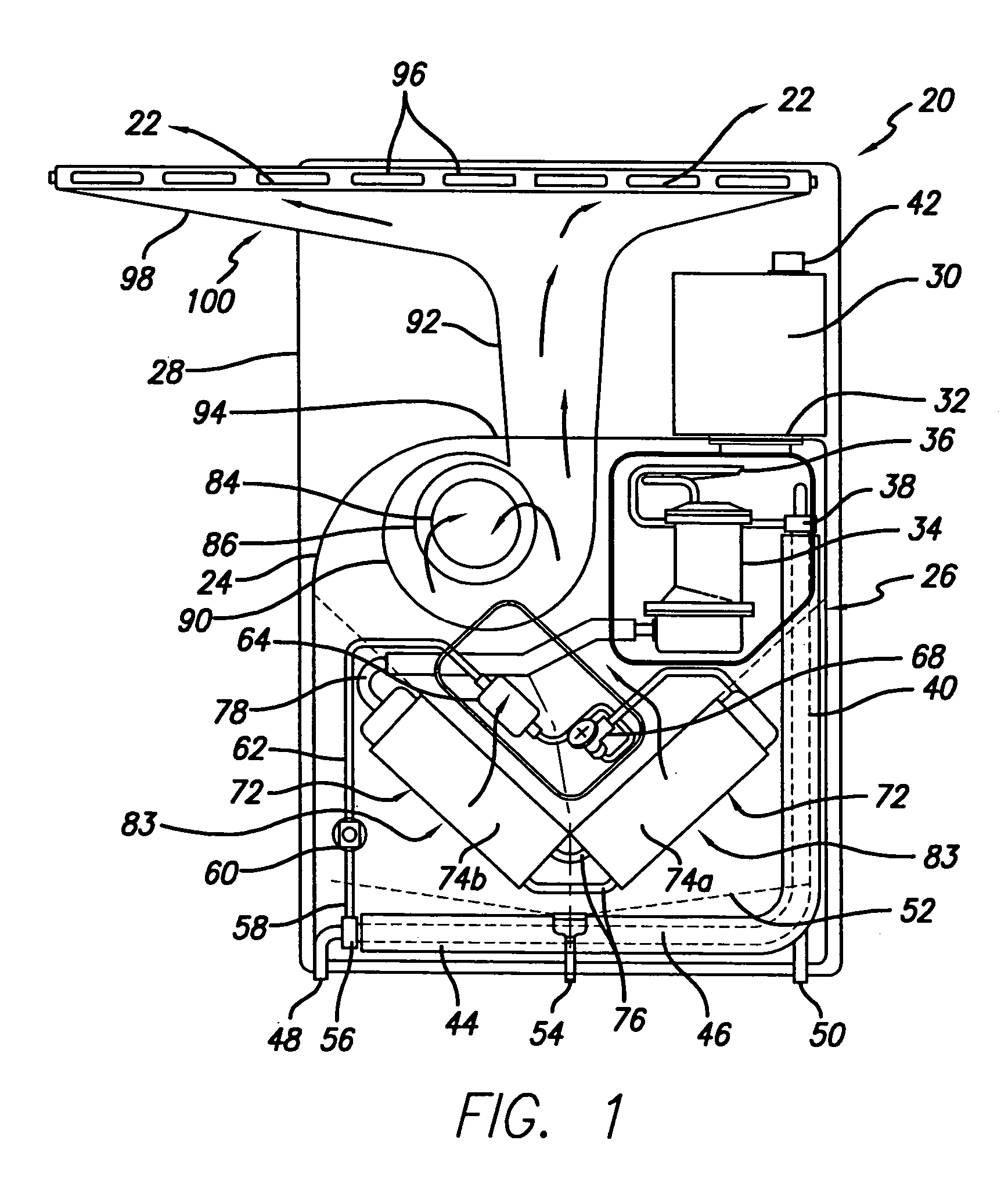
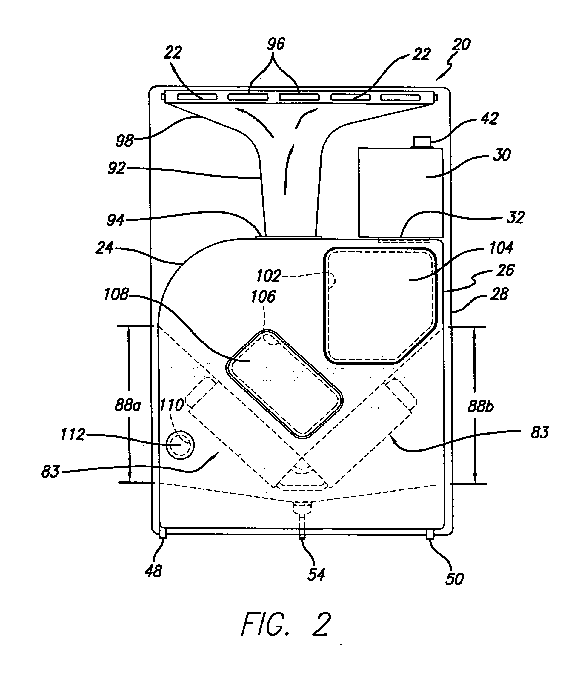
[0040] As illustrated in the FIGS. 1-8, in a first embodiment, the galley cooling system 20 supplies cool air 22 for point-of-use cooling of an aircraft galley cabinet. The galley cooling system includes a housing 24 providing an enclosure portion 26 for the components of the galley cooler, and a back mounting plate 28, to which some of the components of the galley cooling system are mounted. The galley cooling system includes an electrical power supply 30, connected by electrical connector 32 to a compressor motor 34, which compresses a refrigerant coolant and delivers the compressed refrigerant coolant through tubing 36 to an inlet 38 of a condenser 40.

[0041] The electrical power supply has an input connector 42 connectable to one or more electrical cables (not shown) for supplying electrical power and electrical control signals for controlling the operation of the galley cooler, such as the speed of operation of the galley cooling system compressor motor and an air impeller motor...

second embodiment

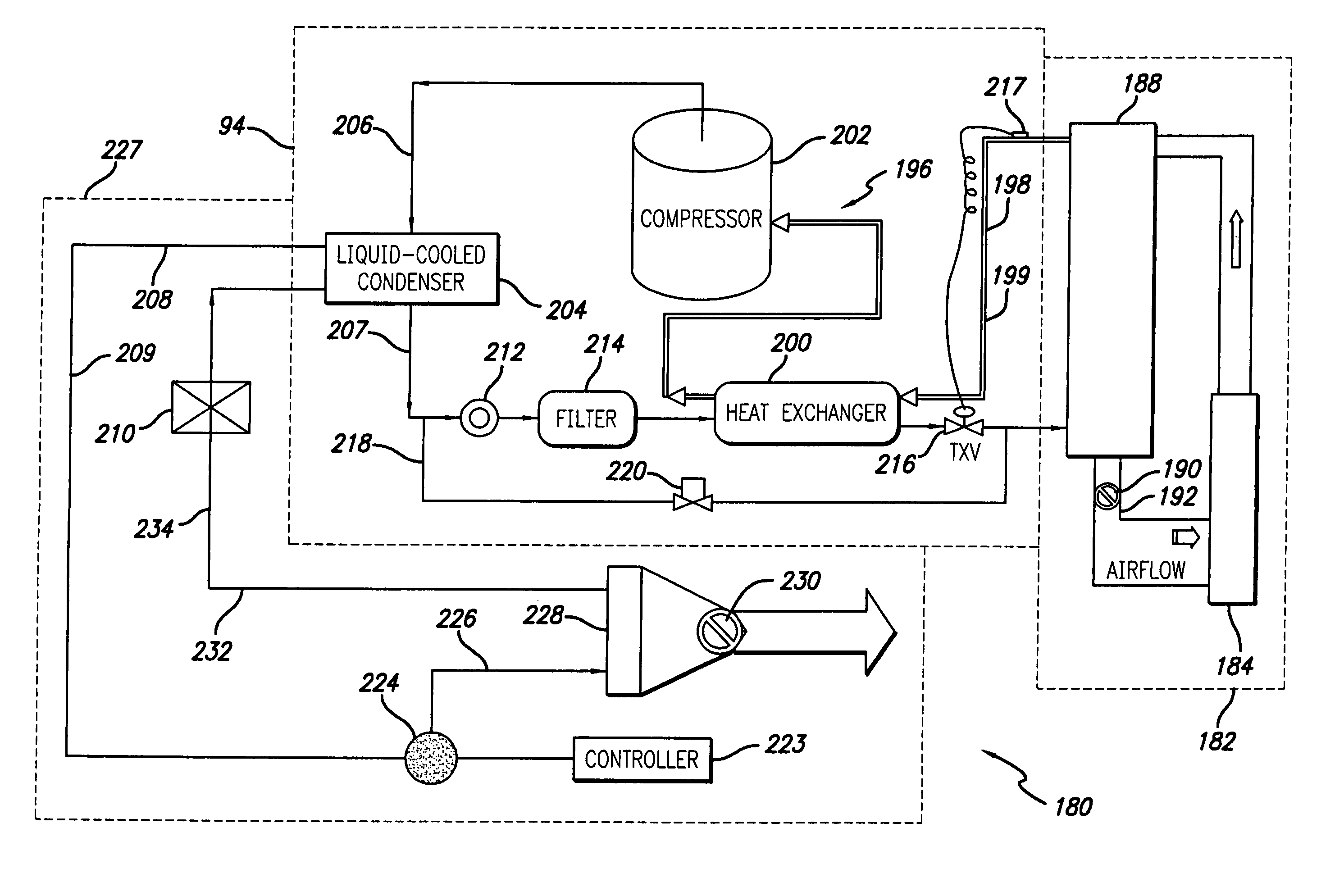
[0051] Referring to FIGS. 9, 10, 11 and 12, in a second embodiment according to the invention, a liquid condensing air chilling system (LCACS) 180 according to the invention includes at least one point-of-use galley cooling unit 182 having at least one galley plenum 184 for receiving at least one galley cart (not shown), and at least one heat exchanger 188 which is typically an evaporator within the galley plenum 184. A galley blower 190 or fan is typically provided in ducting 192 between the heat exchanger 188 and the galley plenum 184 to direct a flow of cooling air from the heat exchanger 188 through the one or more galley carts. The one or more heat exchangers 188 receive an intermediate working fluid 198 such as a refrigerant or other heat transfer fluid from at least one remote liquid condensing chiller subsystem 194. The refrigerant is typically a hydrofluorocarbon refrigerant such as that sold under the name HFC-134a available from DuPont, or sold under the name MEFOREX 134a...


PUM


Abstract

In the improved cooling system for a commercial aircraft galley, heat is transferred from a galley food cart by a point-of-use heat exchange system to a liquid cooled condenser. Liquid coolant for the liquid cooled condenser is circulated in a liquid coolant loop to a heat exchanger expelling heat for cooling the liquid coolant. The liquid coolant may be water or a mixture of water and glycol. A flow of cooling air from a heat exchanger cooled by the liquid cooled condenser is cycled through an air over system, through an air through system, or from a thermal convection air cooling system providing at least one cooled galley food cart surface to provide cooling. Heat may be transferred from a plurality of galley food carts to the circulating liquid coolant.

Description

BACKGROUND OF THE INVENTION [0001] 1. Field of the Invention [0002] This invention relates to transport aircraft galley systems, and more particularly, to systems to cool food carts prior to service by the cabin attendants. [0003] 2. General Background and State of the Art [0004] Aircraft galley systems for modern transport aircraft incorporate food carts which are cooled to prevent food spoilage prior to use by the cabin attendants for distribution of food to the passengers. These food carts have in the past been interfaced with cold air supply systems in the galley designed to cool the interiors of the food carts. Such cool air distribution systems were generally co-located with the balance of the galley and interface with the food carts by means of gaskets connecting the food carts to a plenum providing the cool air. Conventional galley refrigeration systems typically utilize self contained air chillers which provide the cooled air directly to the food carts or refrigerated compa...

Claims


Application Information

Patent Timeline
IPC IPC(8): B60H1/00B60H1/32B64D11/04B64D13/06F25B39/04F25D17/04F25D19/00
CPCB60H1/00014B60H1/00885B60H2001/00928F25D19/003B64D13/06B64D2013/0629F25D17/04B64D11/04B60H1/32281Y02T50/50
Inventor RIGNEY, RICHARD N.OSWALD, IAN D.
Owner BE INTPROP
Why Eureka
Try Eureka