Solar cell assembly

Inactive Publication Date: 2005-09-29
THE BOEING CO
View PDF13 Cites 147 Cited by
  • Summary
  • Abstract
  • Description
  • Claims
  • Application Information

AI Technical Summary

Problems solved by technology

Collector grids have conventionally been metallic grids that can obscure the solar cell, resulting in a loss of efficiency.
Such an arrangement eliminates the need for a separate cover glass and a cover glass adhesive that may darken and thereby reduce efficiency thr

Method used


Image

  • Solar cell assembly
  • Solar cell assembly
  • Solar cell assembly

Examples


Embodiment Construction

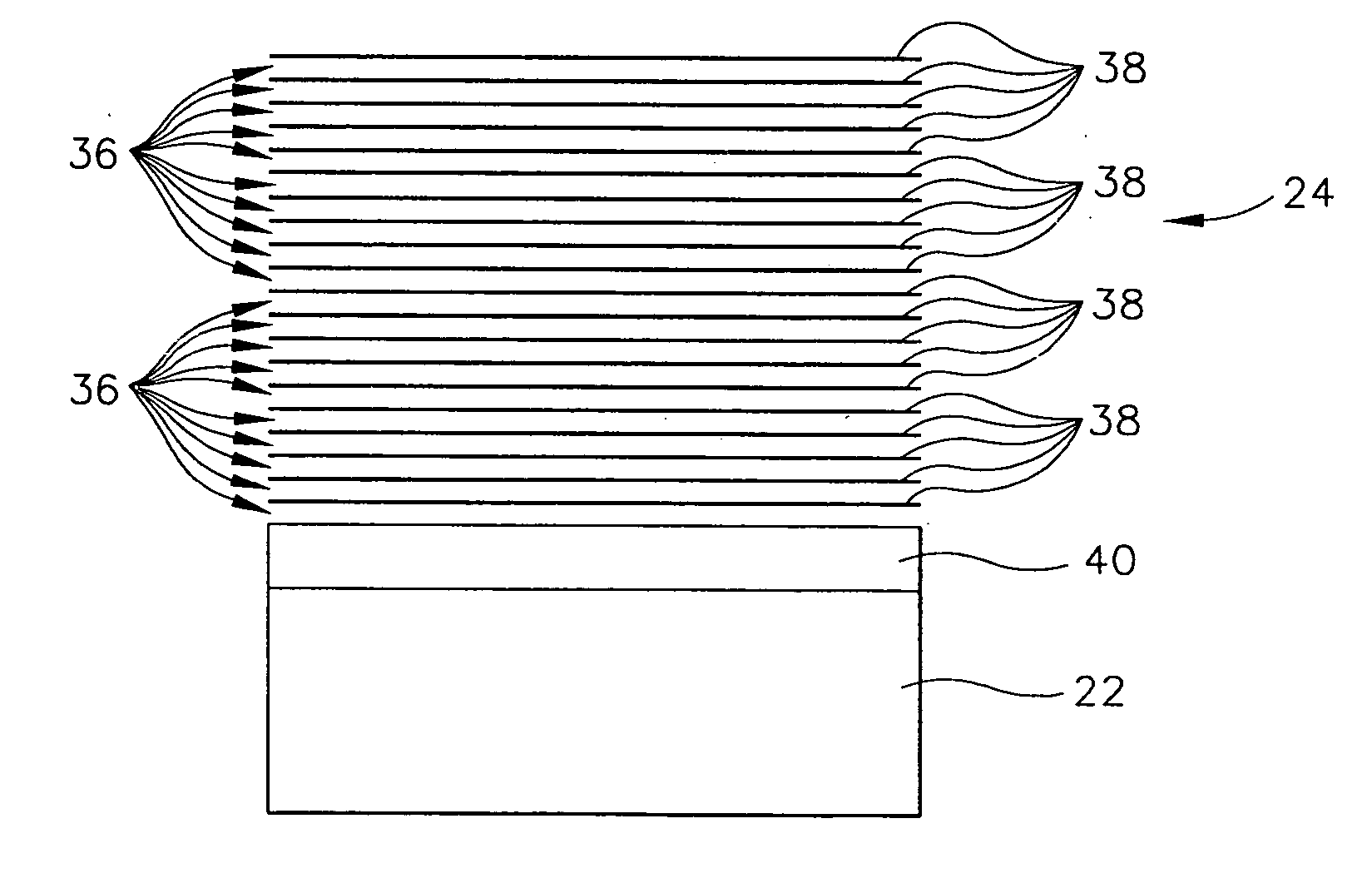
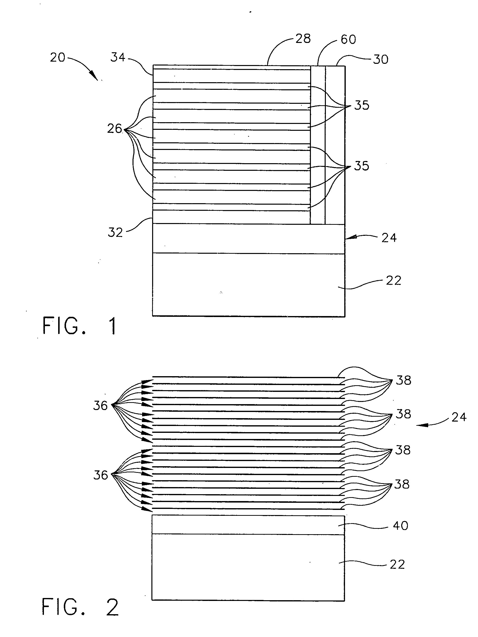
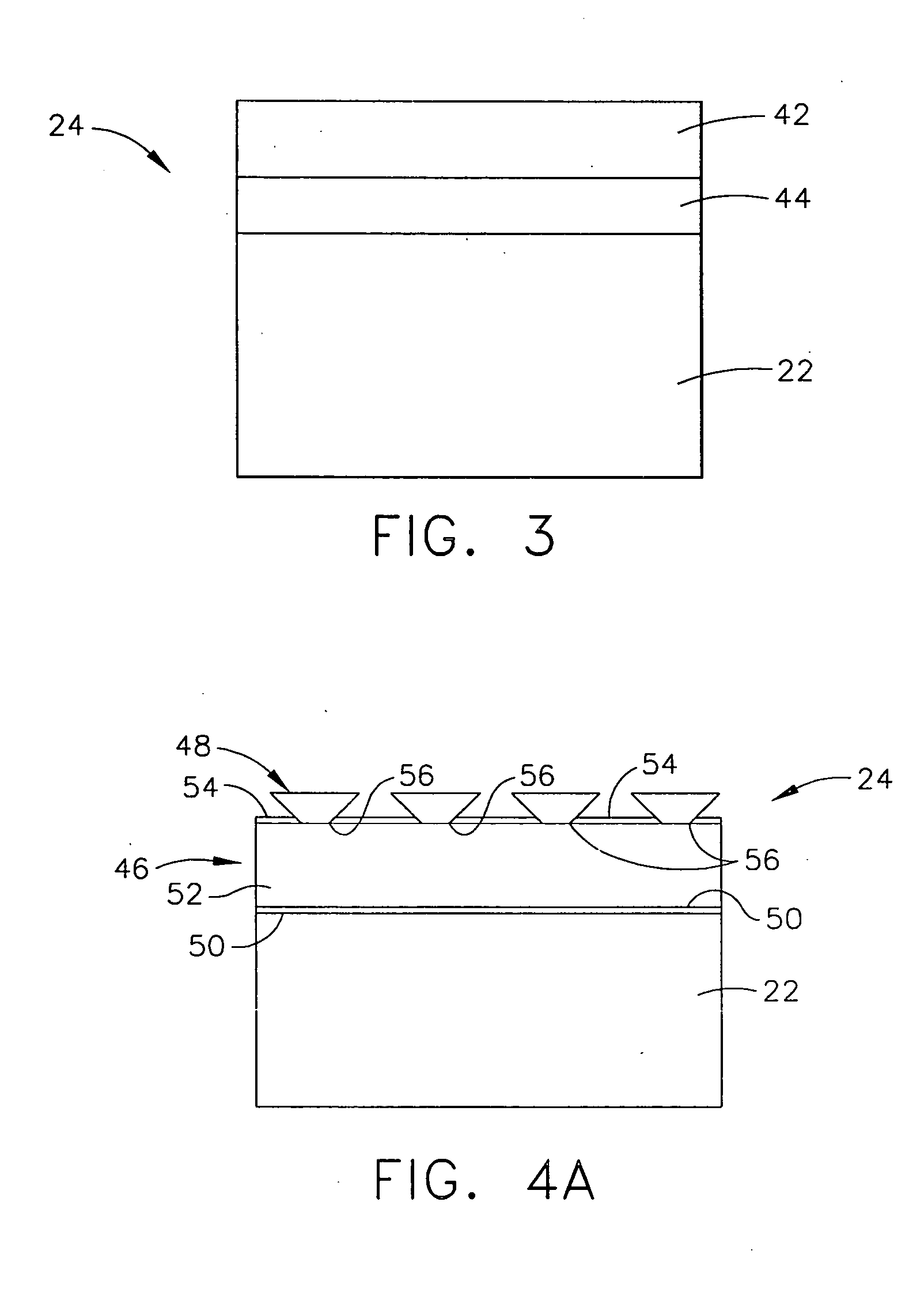
[0014] Referring now to the drawings, and more specifically to FIG. 1, a solar cell assembly of the present invention is designated in its entirety by the reference numeral 20. The solar cell assembly 20 generally includes a transparent substrate 22, a transparent conductive coating (TCC, generally designated by 24) formed on and in intimate contact with the transparent substrate, a plurality of GaInN junction layers 26 formed successively on the TCC, and a metallization layer 28 formed on the GaInN junction layers. The solar cell assembly 20 also includes a conventional metal current collector bus 30. Although the metal current collector bus 30 is shown in FIG. 1 in a back contact solar cell arrangement, the bus 30 may alternatively be arranged as a front contact without departing from the scope of the present invention. In some embodiments, a GaN junction layer 32 is formed on the TCC 24 between the TCC and the GaInN junction layers 26. Additionally, in some embodiments, an indium...


PUM


Abstract

A multi-junction solar cell assembly includes a transparent substrate and a transparent conductive coating formed on the transparent substrate. The transparent conductive coating includes gallium nitride. The solar cell assembly also includes a plurality of gallium indium nitride junction layers formed successively on the transparent conductive coating, and a metallization layer formed on the plurality of gallium indium nitride junction layers.

Description

BACKGROUND OF THE INVENTION [0001] The present invention relates generally to solar cells, and more specifically to solar cells including transparent conductive coatings. [0002] Solar cells typically include a collector grid for conducting solar photon-generated currents from the surface of the cell. Collector grids have conventionally been metallic grids that can obscure the solar cell, resulting in a loss of efficiency. To reduce obscuration, some known solar cells use a transparent conductive coating (TCC), such as gallium nitride (GaN), as the collector grid. Currently, TCCs are being used to improve the efficiency of gallium arsenide (GaAs) solar cells. Some known GaAs solar cells include a transparent substrate, a TCC formed on the transparent substrate, and the GaAs cell formed on the TCC. Such an arrangement eliminates the need for a separate cover glass and a cover glass adhesive that may darken and thereby reduce efficiency through solar obscuration. However, even GaAs sol...

Claims


Application Information

Patent Timeline
IPC IPC(8): H01L31/0352H01L31/068H01L31/072H01L31/18
CPCH01L31/022466H01L31/0725Y02E10/544H01L31/184H01L31/1884H01L31/0735Y02E10/547
Inventor BIANCHI, MAURICE PETER
Owner THE BOEING CO
Why Eureka
Try Eureka