Electromagnetic damper

a technology of electromagnetic shock absorber and damper, which is applied in the direction of shock absorbers, machine supports, mechanical equipment, etc., can solve the problems of affecting the performance of the motor, affecting the efficiency of the motor, so as to increase the productivity increase the durability of the electromagnetic shock absorber, and speed up the heat radiation of the motor

Inactive Publication Date: 2005-09-29
KYB CORP +1
View PDF12 Cites 28 Cited by
  • Summary
  • Abstract
  • Description
  • Claims
  • Application Information

AI Technical Summary

Benefits of technology

[0024] An advantage of the present invention is to hasten heat radiation of a motor and to prevent the motor from being subjected to damage which may arise resulting from the temperature rise exceeding the temperature rating of the motor.
[0025] A further advantage of the present invention is to increase durability of an electromagnetic shock absorber, further to increase productivity of the electromagnetic shock absorber, and to decrease production costs of the electromagnetic shock absorber.
[0026] In order to achieve the advantages described above, the electromagnetic shock absorber according to the present invention comprises: a shock absorber body which makes telescopic motion in response to an input from outside; a ball screw mechanism which is arranged at the shock absorber body, converts the telescopic motion into rotary motion, and is composed of a ball nut and a screw shaft; a motor which is provided coaxially with the shock absorber body and generates electromagnetic resistance to oppose against the rotary motion

Problems solved by technology

However, in such a suspension unit in which magnet coils are built in a hydraulic shock absorber, a hydraulic pressure, a power source, and the like are required, whereby it is complicated in structure and it is disadvantageous in respect of the costs.
However, it is feared that the following problems may arise if the electromagnetic shock absorber which generates electromagnetic resistance by converting telescopic motion of the shock absorber body into rotary motion of the motor 50 by the ball screw mechanism as described above is actually applied to a vehicle.
Thus, it is feared that for example, rainwater or muddy water permeates the motor 50 and the motor short-circuits and is damaged, thereby spoiling the functions of the motor 50 or the like.
Especially, if the electromagnetic shock absorber is arranged as a shock absorber for a vehicle at a part having an insufficient space which is

Method used


Image

  • Electromagnetic damper
  • Electromagnetic damper
  • Electromagnetic damper

Examples


second embodiment

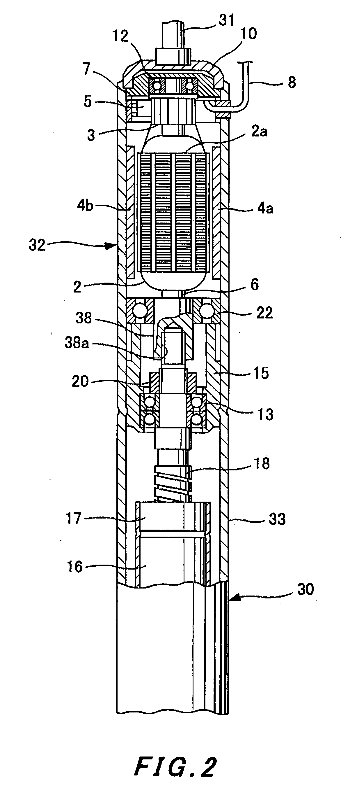
[0075] A second embodiment will subsequently be described with reference to FIG. 2.

[0076] In this embodiment, the shock absorber body 30 comprises an external cylinder 33 which extends up to the motor 32.

[0077] In the external cylinder 33 similarly to the cover 1, a frame, which covers the rotor and stator of the motor 32 from the outside, and components, which are essential for a yoke, are formed in one united body. The permanent magnets 4a and 4b are directly installed at the internal circumference of the external cylinder 33 so as to form the stator of the motor 32.

[0078] The shaft 6 of the motor 32 is rotatably supported by the ball bearing 22 which is arranged above the bearing retention member 15 installed inside the external cylinder 33. The shaft 6 goes through the ball bearing 22 and projects downward, and a tip of the screw shaft 18 is inserted into an axis hole 38a of a projected section 38. The shaft 6 is connected with the screw shaft 18, for example by spline fit-in,...

first embodiment

[0080] Other constitution is same as that of the first embodiment and the same reference symbols are attached to the same components.

[0081] Therefore, in this embodiment, the outside of the motor 32 is covered by the extended external cylinder 33 of the shock absorber body 30 and thus the motor 32 is protected.

[0082] The frame of the motor 32 and the components essential for a yoke are formed in one united body at a part of the external cylinder 33 which covers the motor 32 from the outside. Therefore, it facilitates assembly of the motor into the electromagnetic shock absorber and it also improves the workability and productivity.

[0083] The present invention is not restricted to the embodiments described above. It is obvious that the present invention includes various improvement and modification which can be made by a person skilled in the art within a scope of technical ideas given in the following claims.


PUM


Abstract

A shock absorber body 30 which makes telescopic motion in response to an input from outside has a ball screw mechanism 16 which converts the telescopic motion into rotary motion and is composed of a ball nut 17 and a screw shaft 18. A motor 32 is provided coaxially with the shock absorber body 30. The motor 32 generates electromagnetic resistance to oppose against the rotary motion which inputs into a rotary shaft 6 of the motor 32. A cylindrical member 1 or 23 which covers the shock absorber body 30 and the motor 32 from outside and whose part covering the motor 30 also serves as a motor frame is provided. Damping force which opposes against the telescopic motion of the shock absorber body 30 is generated according to electromagnetic force of the motor 32.

Description

TECHNICAL FIELD [0001] The present invention relates to an electromagnetic shock absorber which converts telescopic motion of a shock absorber body into rotary motion of a motor utilizing a ball screw mechanism and damps vibration utilizing electromagnetic resistance generated by the motor. BACKGROUND ART [0002] A suspension unit for a vehicle in which a hydraulic shock absorber is arranged, in parallel with a suspension spring, between a car body and an axle is widely known. [0003] Further, Japanese Patent Laid-Open Publication No. 5-44758A has disclosed a suspension unit in which magnet coils are built in a part of a hydraulic shock absorber. In this suspension unit, coils are attached to a cylinder of the hydraulic shock absorber and magnets are attached to a piston rod, respectively, and an electric current is applied to the coils, thereby generating driving force (electromagnetic force) along the direction of a stroke of the piston rod so as to control the quantity of telescopi...

Claims


Application Information

Patent Timeline
IPC IPC(8): F16F15/03
CPCF16F2232/06F16F15/035F16F6/00F16F7/00F16F15/03
Inventor KONDO, TAKUHIROMATSUMAE, TAROSUDA, YOSHIHIRO
Owner KYB CORP
Why Eureka
Try Eureka