End cap for segmented stator

a stator and end cap technology, applied in the direction of windings, dynamo-electric components, magnetic circuit shapes/forms/construction, etc., can solve the problems of inconvenient routing of wires on the outside portion of the stator, poor winding characteristics and inefficient density of the winding coil. achieve the effect of facilitating wire winding

Active Publication Date: 2005-09-29
HERMETIC MOTORS LP
View PDF34 Cites 47 Cited by
  • Summary
  • Abstract
  • Description
  • Claims
  • Application Information

AI Technical Summary

Benefits of technology

[0013] A stator for an electromagnetic machine includes a plurality of discrete and individually wound stator segments having end caps positioned on the segments. In one aspect, the end caps have legs for positioning the end cap on the segments with an interference fit. In another aspect, the end caps have angled surfaces to facilitate winding of wire on the segments. In another aspect, the end caps have male and female couplings that mate together to couple adjacent segment

Problems solved by technology

Therefore, any problems with the end caps can produce poor winding characteristics in the winding coils, such as undesirable overlap of the winding coils or inefficient density of the winding coils about the tooth portions.
In a compressor motor, however, routing wires on the outside portion of the stator is not desirable.
Because the interconnect wires routed on a stator are positioned adjacent one another, a large voltage differential between the adjacent interconnect wires can produce phase-on-phase conditions in the motor and can cause premature failure of the insulation on the wires.
The waveform from the PWM drive may have high voltage spikes on the leading and trailing edges of the waveform, creating the need to separate the phase wires.
Unfortunately, such secondary insulation can increase the manufacturing costs and production time of the motor.
In addition, conventional segmented stators do not provide a ready way to axially align the segments to preven

Method used


Image

  • End cap for segmented stator
  • End cap for segmented stator
  • End cap for segmented stator

Examples


Embodiment Construction

[0031] A. Stator Assembly

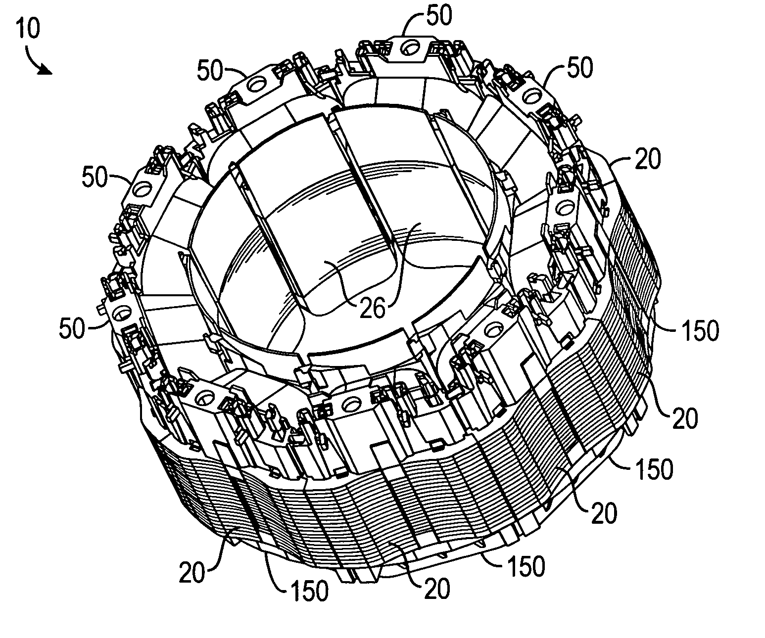
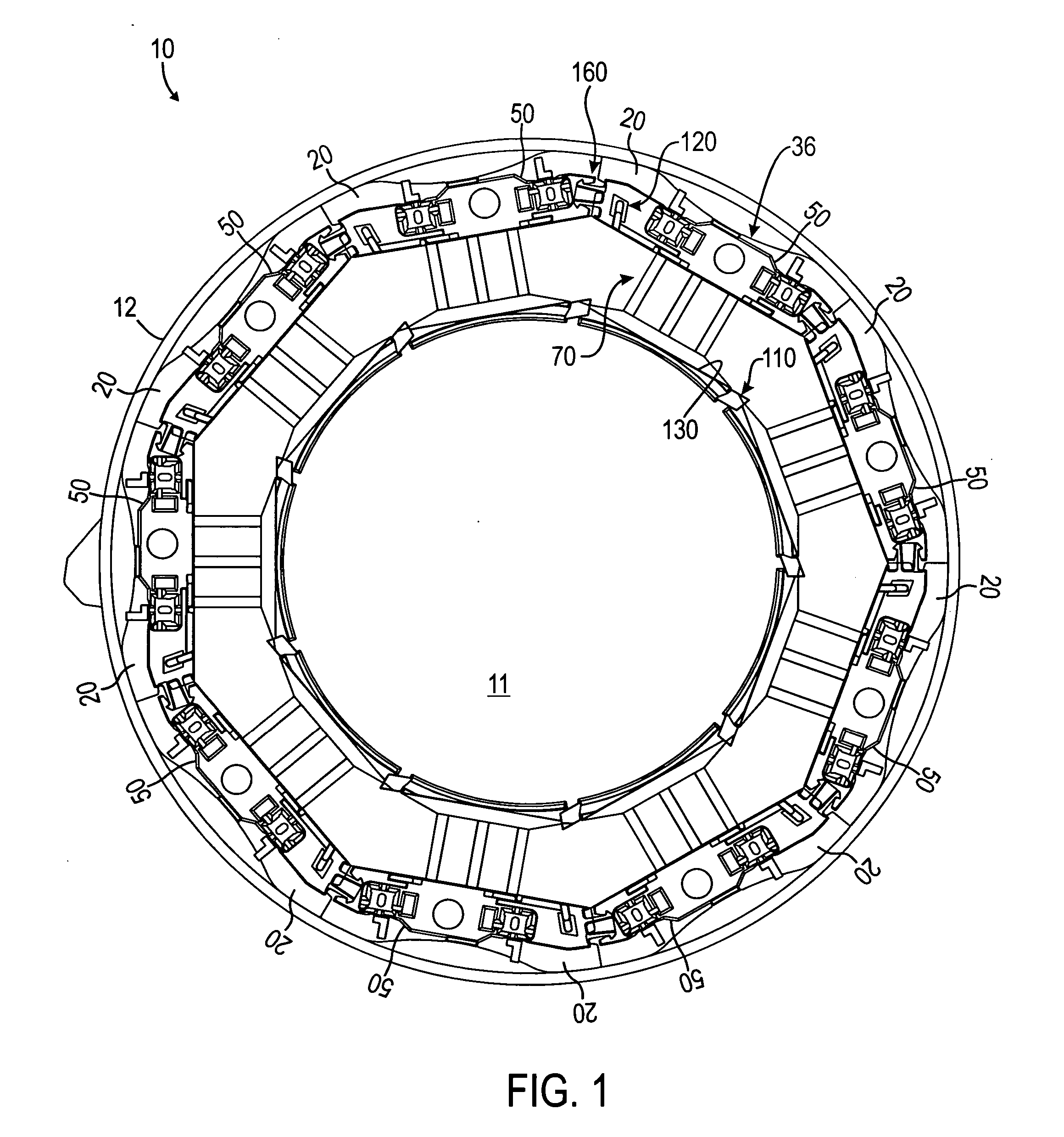
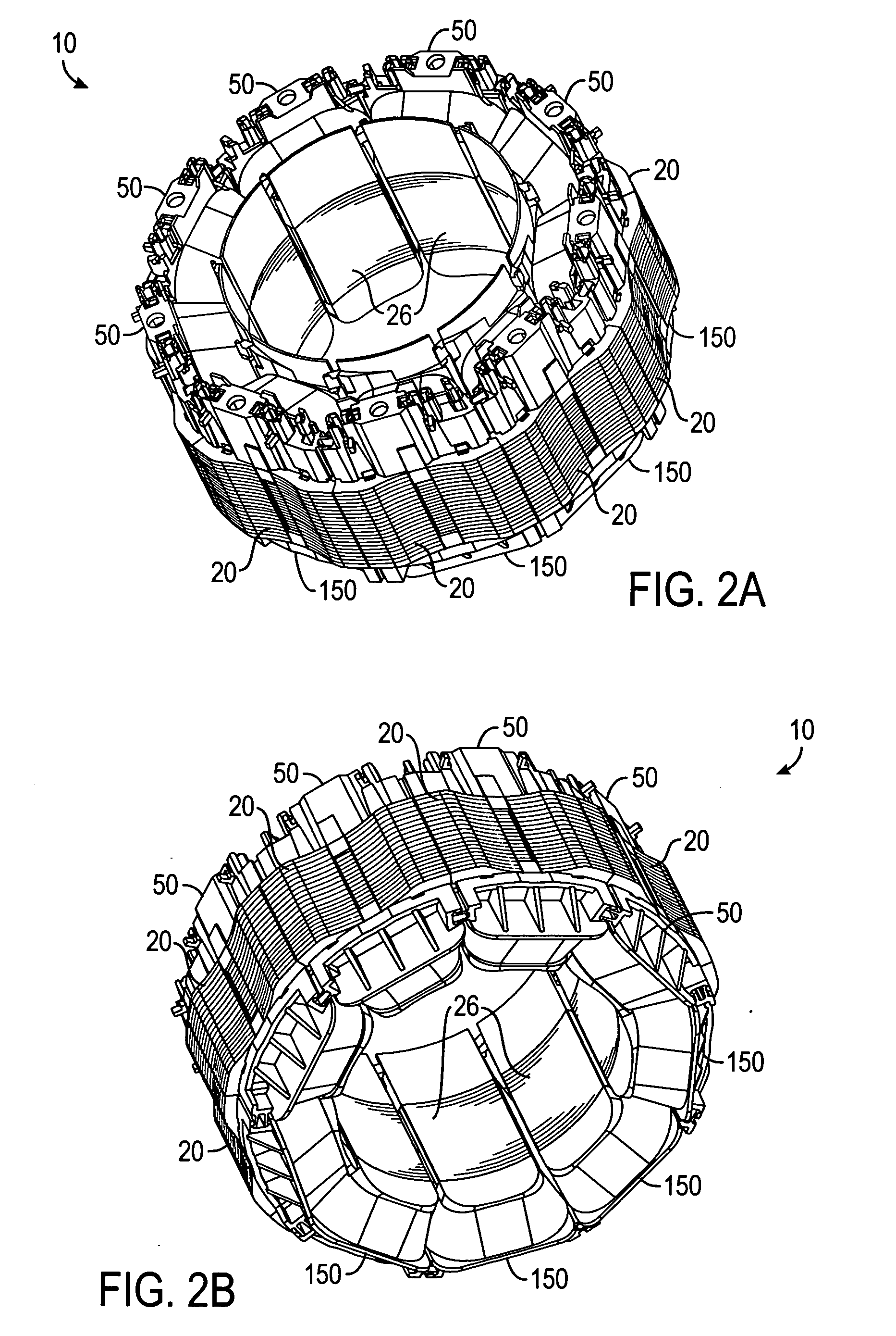
[0032] Referring to FIGS. 1 and 2A-2B, an embodiment of a segmented stator assembly 10 according to certain teachings of the present disclosure is illustrated. FIG. 1 illustrates a plan view of the disclosed stator assembly from the lead-end, and FIGS. 2A and 2B illustrate perspective views of the disclosed stator assembly 10 from the lead-end and the base-end, respectively. The disclosed stator assembly 10 is of the “loose” segmented stator type. The disclosed stator assembly 10 can be used in variable speed motor applications, such as a hermetic compressor for a refrigeration system of a vehicle or a residence, for example. However, certain teachings of the present disclosure can be used with other types of stator and used in other motor applications.

[0033] The segmented stator assembly 10 includes a plurality of discrete stator segments 20. The segments 20 have lead end caps 50 and base end caps 150. In the present example, the segmented stator assembly...


PUM

PropertyMeasurementUnit
Angleaaaaaaaaaa
Areaaaaaaaaaaa

Abstract

A stator for an electromagnetic machine includes a plurality of discrete and individually wound stator segments having end caps positioned on the segments. The end caps have legs for positioning the end cap on the segments with an interference fit. The end caps have angled surfaces to facilitate winding of wire on the segments. The end caps have male and female couplings that mate together to couple adjacent segments together. The end caps have fingers and slots for aligning the segments on substantially the same plane. The end caps have wire isolation features, including hooks, shelves and ledges, for separating the interconnect wires routed on the stator to electrically interconnect the segments. The segments include scalloped contours on their outer edges for draining oil, and the end caps have passages for draining oil.

Description

CROSS-REFERENCE TO RELATED APPLICATIONS [0001] This application is filed concurrently with U.S. Patent Application having Express Mail No. EV 317623705 US, Attorney Docket No. 10800.0048.NPUS00, and entitled “End Cap for Interconnecting Winding Coils of Segmented Stator to Reduce Phase-on-Phase Conditions and Associated Methods;” U.S. Design Application having Express Mail No. EV 317623609 US, Attorney Docket No. 10800.0051.NPUS00, and entitled “Lead End Cap for Segmented Stator;” U.S. Design Application having Express Mail No. EV 317623714 US, Attorney Docket No. 10800.0050.NPUS00, and entitled “Base End Cap for Segmented Stator;” and U.S. Design Application having Express Mail No. EV 317623688 US, Attorney Docket No. 10800.0047.NPUS00, and entitled “Contoured Stator,” which disclose related subject matter.FIELD OF THE PRESENT DISCLOSURE [0002] The subject matter of the present disclosure relates to stator assemblies for electromagnetic machines. More particularly, the subject matt...

Claims


Application Information

Patent Timeline
IPC IPC(8): H02K1/14H02K3/32H02K3/38H02K3/52
CPCH02K1/148Y10T29/49009H02K3/522H02K3/325
Inventor WANG, WEIRONGROSE, JOHN SCOTTMICHAELS, PAUL G.CARRIER, MARK E.JURKOWSKI, JASON J.
Owner HERMETIC MOTORS LP
Why Eureka
Try Eureka