Apparatus for modulating a light beam

a technology of light beams and apparatuses, applied in the field of modulation of light beams, can solve the problems of limited speed (modulation frequency) of chopping, inability to achieve the level of light output extinction for these half cycles, and inability to achieve the level of light output extinction that is not as good as is desirabl

Inactive Publication Date: 2005-09-29
OPTICAL METROLOGY PATENTS
View PDF13 Cites 7 Cited by
  • Summary
  • Abstract
  • Description
  • Claims
  • Application Information

AI Technical Summary

Benefits of technology

[0035] In a further embodiment there is provided a laser blocking system comprising a modulator as defined above and a means for safety terminating a zero order output, a...

Problems solved by technology

Mechanical chopping of the beam suffers from limitations to the stability of the frequency of chopping, limitations to the speed (modulation frequency) of chopping which is possible, and produces a periodic intensity profile which departs from an ideal square wave or sinusoidal wave intensity variation with time.
This frequency can be high for some applications, and for high frequencies it appears that the level of light output extinction for these half cycles may not be as good as is desirable.
Also, at high modulation frequencies the switching time can become significant with respect to the duty cycle off period.
Another possible problem is that in the off state there may be residual optical beam scatter.
However, they suffer from being limited to low frequencies (typically much lower than 3 kHz), are confined to small scan angles (typically much less than 1 mrad in the re...

Method used


Image

  • Apparatus for modulating a light beam
  • Apparatus for modulating a light beam
  • Apparatus for modulating a light beam

Examples


Embodiment Construction

[0040] The invention provides an apparatus and method for modulating a light beam, which may be used for various purposes including that of inducing a modulation of the optical and / or electronic properties of a target material by an optical means.

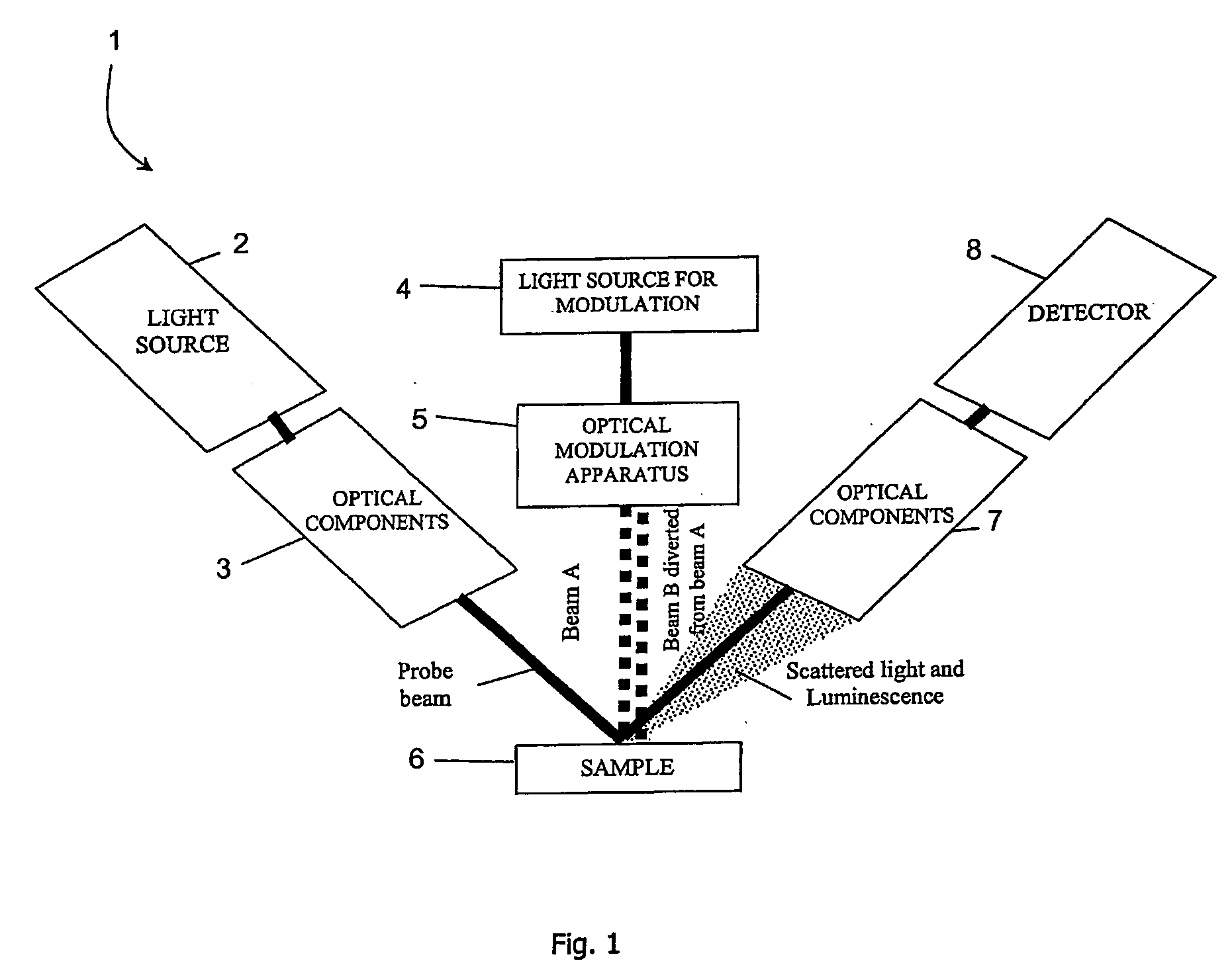
[0041] Components of the system of the invention are those which produce, and perform the modulation of, a light beam incident on a sample material, as follows. In this specification, optical coupling may use free space components, or suitable waveguides.

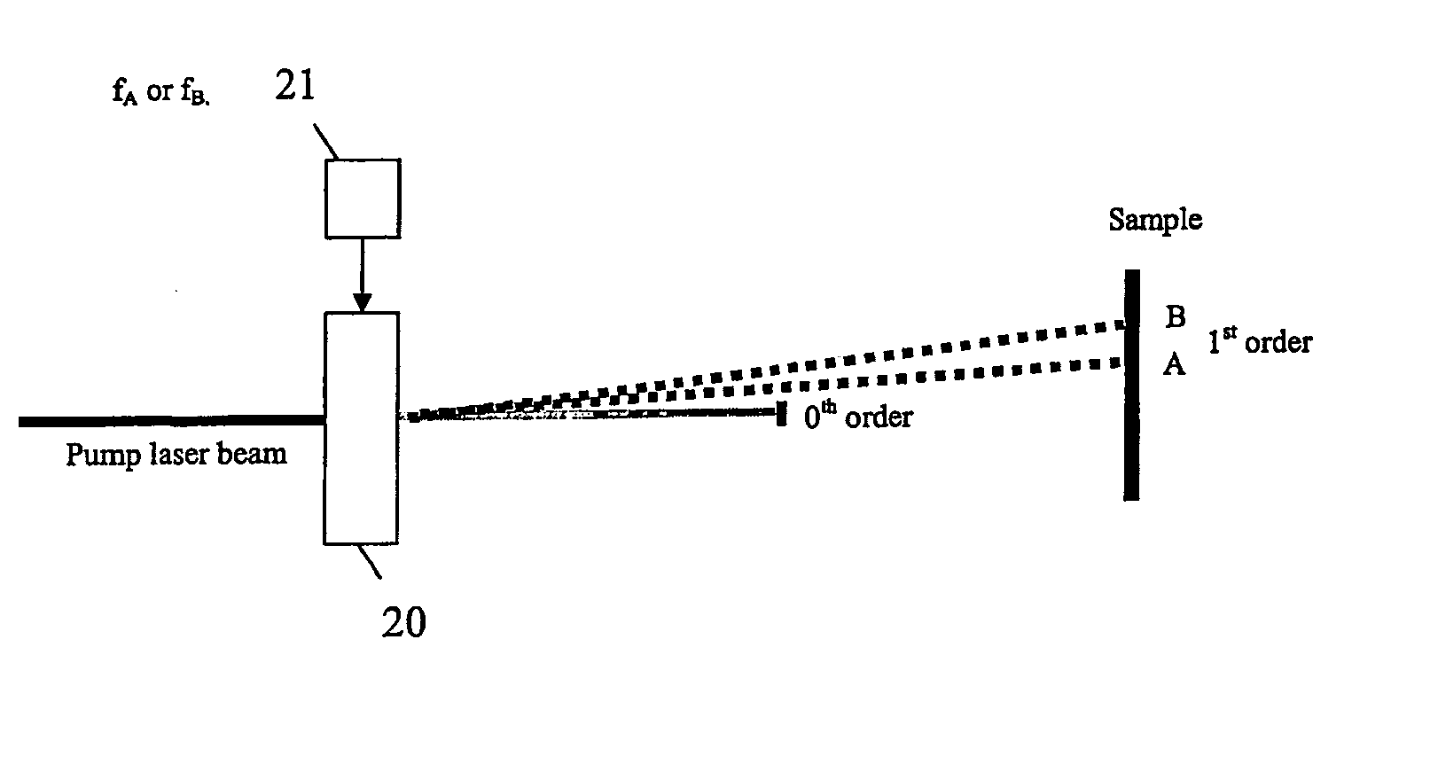
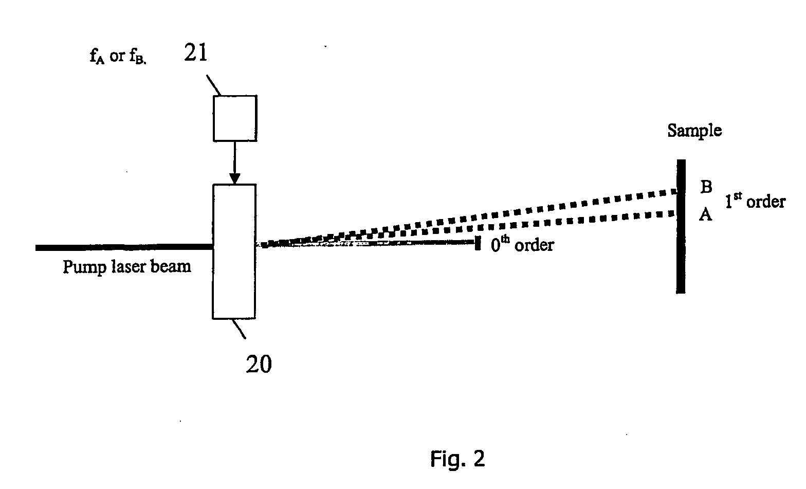
[0042] A light source, called the pump light source, produces a light beam having a single wavelength or a narrow spectrum of wavelengths, and optical components for shaping the light beam and coupling it to other components of the system. A pump beam optical intensity modulator between the pump light source and the sample modulates the intensity of the light steered to the point of incidence of the pump beam on the sample by alternating the position of incidence of the pump beam on the s...


PUM


Abstract

A modulation spectroscopy system (1) has an acousto-optic modulator (5) providing a pump beam onto a sample. The modulator receives a light beam from a source (4) and diffracts it to provide an output which is the first order beam, the zeroth order or undeflected beam being terminated and the 2nd and higher orders being negligible and terminated also. The modulator is driven alternately by two drive frequencies at a modulation or toggle frequency. The first order output is at one angle for a first drive frequency and at another angle for the other drive frequency. The duty cycle of alternating between the different drive frequencies sets the output beam position duty cycle for incidence at two different spots on the sample. Also, either or both beams may be position and/or intensity varied by control of the modulator drive frequencies and their amplitudes.

Description

FIELD OF THE INVENTION [0001] The invention relates to modulation of light beams. PRIOR ART DISCUSSION [0002] Modulation spectroscopy is a class of spectroscopy in which the reflectance (or transmission) of a material such as a semiconductor, an organic material, or a polymer is altered at some parts of the electromagnetic spectrum by means of an external perturbation. Generally, this perturbation is applied in a periodic manner, such that the reflectance (or transmission) of the semiconductor at the wavelengths where it changes in response to the external perturbation periodically alternates between the value in the absence of external perturbation and that which it has in the presence of the external perturbation. In many methods of modulation spectroscopy, the perturbation is optically applied by means of a light beam. In such methods, the light beam used to perform the spectroscopy measurement is often referred to as the “probe” beam and the light beam which perturbs the reflect...

Claims


Application Information

Patent Timeline
IPC IPC(8): G01J3/02G01J3/12G01J3/433G02F1/29G02F1/33
CPCG01J3/02G01J3/0224G01J3/1256G02F1/33G01N2021/1725G02F1/292G01J3/433
Inventor MURTAGH, MARTIN EDWARDKELLY, PATRICK VINCENT
Owner OPTICAL METROLOGY PATENTS
Why Eureka
Try Eureka