Magnetic disk apparatus with heating device and magnetic head slider used therefor

a technology of magnetic disk and heating device, which is applied in the direction of maintaining head carrier alignment, recording information storage, instruments, etc., can solve the problems of reducing the life of recording and reproducing elements, increasing electric power consumption, and shortened life, and achieves high recording density, high reliability, and reduced electric power consumption

Inactive Publication Date: 2005-09-29
WESTERN DIGITAL TECH INC
View PDF19 Cites 64 Cited by
  • Summary
  • Abstract
  • Description
  • Claims
  • Application Information

AI Technical Summary

Benefits of technology

[0032] According to the invention, it is possible to obtain a magnetic disk apparatus and a magnetic head slider to be able to achieve reduction in electric power consumption while ensuring a high recording density and a high reliability.

Problems solved by technology

In keeping with this, there is caused a problem that a large quantity of electric power is supplied to the heating device to lead to an increase in electric power consumption.
Also, recording and reproducing elements making use of magnetoresistiveness to hold a mainstream at present are featured to be weak in resisting a thermal load and to be shortened in life when exposed to high temperature for a long period of time.
Accordingly, when a heating device is arranged near to a recording and reproducing element and electric power applied to the heating device is large, there is a fear that the recording and reproducing element is reduced in life by heating.
On the other hand, with the magnetic disk apparatus in Patent Document 2, since a Peltier element is used to control a flying amount of a recording and reproducing element, there is caused a problem that it is practically difficult to incorporate the Peltier element into a magnetic head slider to exercise a necessary control.

Method used


Image

  • Magnetic disk apparatus with heating device and magnetic head slider used therefor
  • Magnetic disk apparatus with heating device and magnetic head slider used therefor
  • Magnetic disk apparatus with heating device and magnetic head slider used therefor

Examples


first embodiment

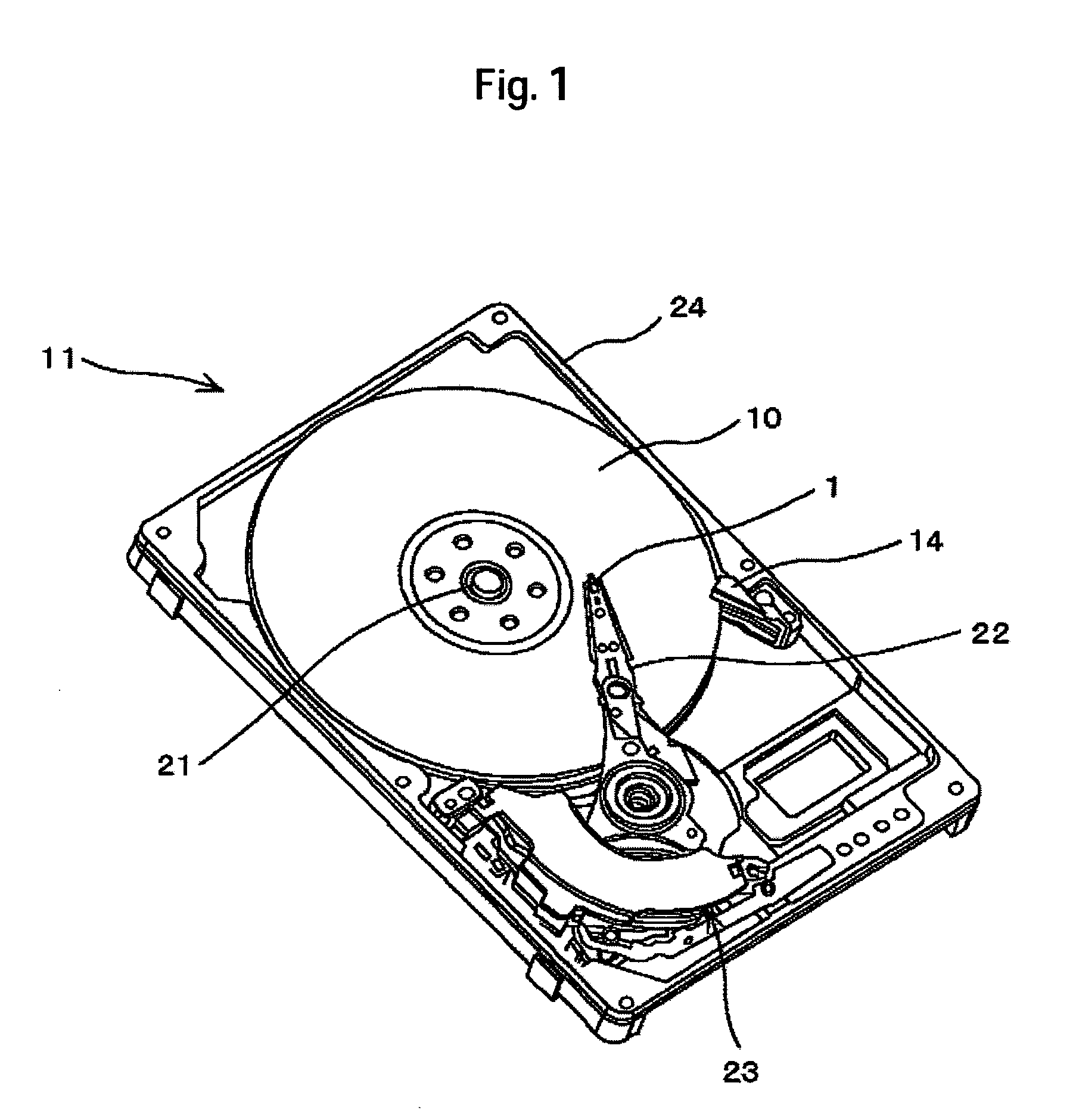
[0045] First, a magnetic disk apparatus according to the invention will be described with reference to FIGS. 1 to 7.

[0046]FIG. 1 shows a schematic construction of a magnetic disk apparatus 11 according to the embodiment. The magnetic disk apparatus 11 comprises a spindle motor 21, a rotatable magnetic disk 2, a magnetic head slider 1 to be able to fly from a surface of the magnetic disk, a turnable actuator 22 mounting the magnetic head slider 1 on one side thereof, and a voice coil motor 23 to drive the actuator 22. The magnetic disk apparatus 11 is provided with a base 24 and a cover (not shown) of a disk enclosure.

[0047] The magnetic head slider 1 mounts thereon a recording and reproducing element to record and reproduce magnetic information. A magnetic disk 10 stores magnetic information and is rotated by the spindle motor 21. The magnetic head slider 1 is mounted to a load beam in the form of a leaf spring, and given a push load on the magnetic disk surface by the load beam. A...

second embodiment

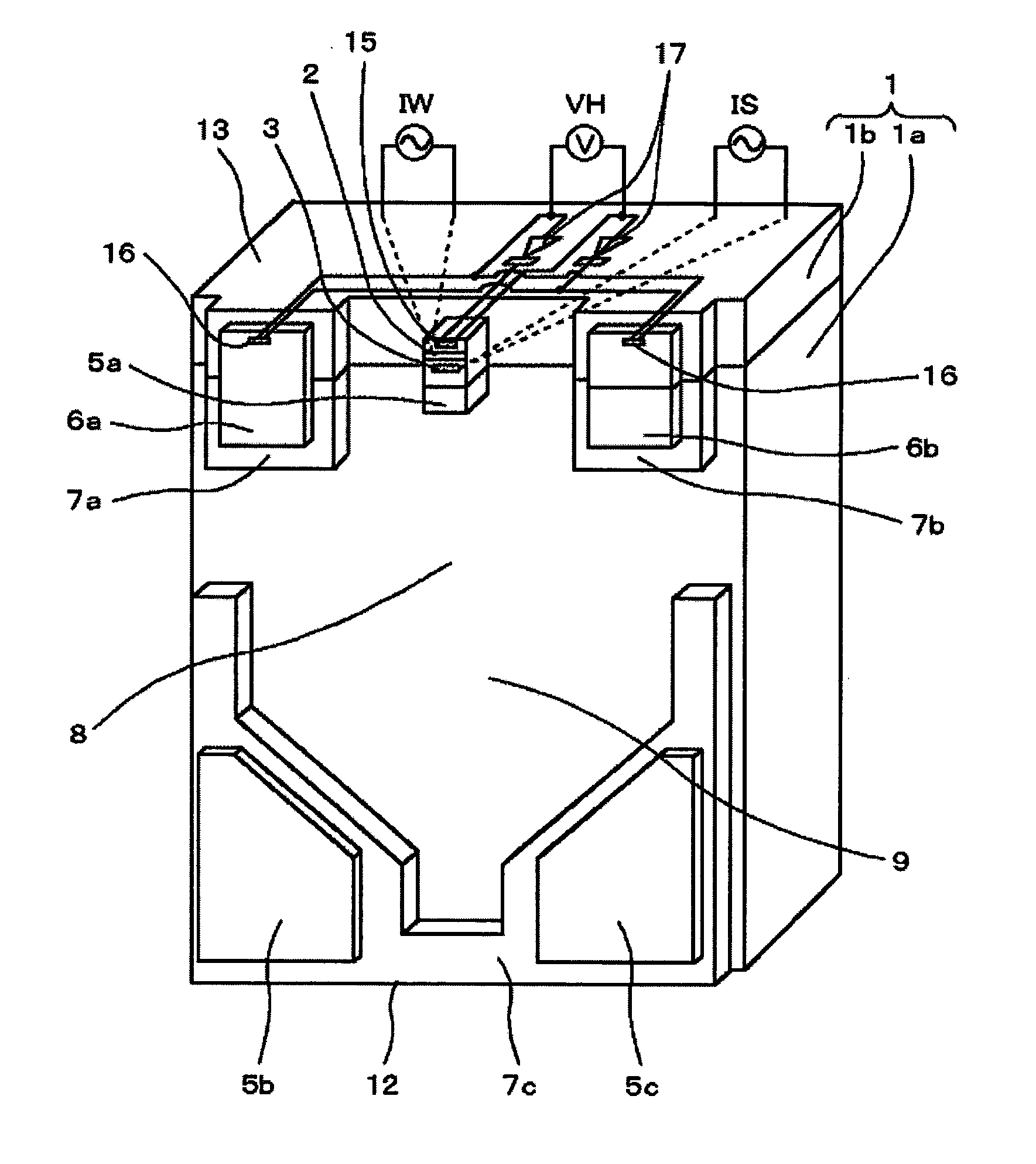
[0095]FIG. 8 is an enlarged, perspective view showing a neighborhood of an outflow end of a magnetic head slider used in a magnetic disk apparatus according to the invention.

[0096] With the magnetic head slider 1 according to the second embodiment, a shallow groove surface 7a is provided centrally on an air outflow end side of a deep groove surface 8, and an element mount surface 5a and ultra-shallow groove surfaces 6a, 6b are provided above the shallow groove surface 7a. The element mount surface 5a has a planar shape such that an upper portion thereof in the figure is narrow (the same width as that in the first embodiment) and a lower portion thereof is wide. The ultra-shallow groove surfaces 6a, 6b are formed adjacent to both sides of a small-width portion of the element mount surface 5a. The same effect as that of the first embodiment is produced in that constitution of the second embodiment, which is common to that of the first embodiment.

[0097] In addition, in the case where ...

third embodiment

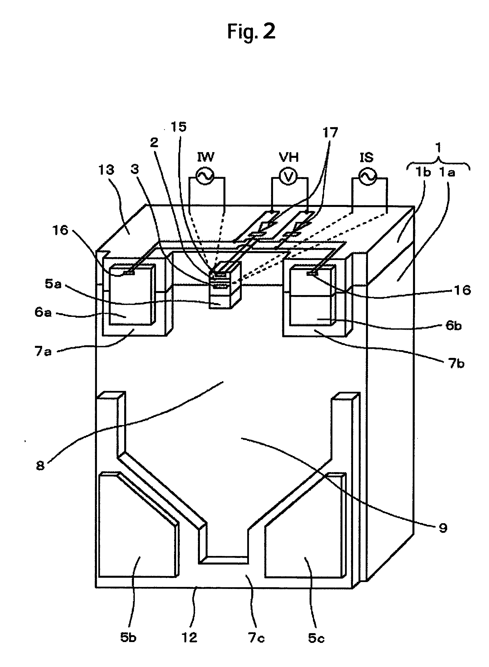
[0098]FIG. 9 is an enlarged, perspective view showing a neighborhood of an outflow end of a magnetic head slider used in a magnetic disk apparatus according to the invention.

[0099] With the magnetic head slider 1 according to the third embodiment, a shallow groove surface 7a is provided centrally on an air outflow end side of a deep groove surface 8, and an element mount surface 5a and ultra-shallow groove surfaces 6a, 6b are provided above the shallow groove surface 7a. The element mount surface 5a is formed above the shallow groove surface 7a to have the same planar dimension as that in the first embodiment. The ultra-shallow groove surfaces 6a, 6b are formed on both sides of the element mount surface 5a with the shallow groove surface 7a therebetween. The same effect as that of the first embodiment is produced in that constitution of the third embodiment, which is common to that of the first embodiment.

[0100] In addition, in the case where portions defining the ultra-shallow gro...


PUM

PropertyMeasurementUnit
depthaaaaaaaaaa
areaaaaaaaaaaa
thicknessaaaaaaaaaa

Abstract

Embodiments of the invention achieve a decrease in electric power consumption while ensuring high recording density and high reliability in a magnetic disk apparatus. In one embodiment, a magnetic disk apparatus comprises a rotatable magnetic disk and a magnetic head slider to be able to fly above a surface of the magnetic disk. The magnetic head slider comprises an air bearing surface, by which the magnetic head slider is caused to fly and come near to the rotating surface of the magnetic disk with a predetermined spacing therebetween, recording and reproducing elements to perform at least one of recording on and reproduction from the magnetic disk, and a heating device to adjust a distance between the recording and reproducing elements and the surface of the magnetic disk. The heating device is mounted such that heating thereof causes a part of the air bearing surface to expand and project to increase a distance between the recording and reproducing elements and the surface of the magnetic disk.

Description

CROSS-REFERENCES TO RELATED APPLICATIONS [0001] This application claims priority from Japanese Patent Application No. JP2004-086020, filed Mar. 24, 2004, the entire disclosure of which is incorporated herein by reference. BACKGROUND OF THE INVENTION [0002] The present invention relates to a magnetic disk apparatus, and is specifically suited to a magnetic disk apparatus provided with a flying-amount adjustment slider having the function of adjusting a distance between a magnetic disk and a magnetic head. [0003] Magnetic disk apparatuses comprise a rotating magnetic disk and a magnetic head slider mounting thereon a recording and reproducing element and supported and positioned radially by a load beam, the magnetic head slider running relatively on the magnetic disk to read and write magnetic information recorded on the magnetic disk. The magnetic head slider flies as an air lubricated bearing due to the wedge film effect of air, so that the magnetic disk and the magnetic head slider...

Claims


Application Information

Patent Timeline
Patent Type & Authority Applications(United States)
IPC IPC(8): G11B5/60G11B15/64G11B17/32G11B21/20G11B21/21
CPCG11B5/6064G11B5/6005G11B5/607G11B5/6082
Inventor KURITA, MASAYUKISHIRAMATSU, TOSHIYAKOHIRA, HIDEKAZUTOKUYAMA, MIKIO
Owner WESTERN DIGITAL TECH INC
Why Eureka
Try Eureka