Solid state electrochemical composite

a solid-state electrochemical and composite technology, applied in the field of solid-state electrochemical devices, can solve the problems of affecting the performance of ionic devices, forming deleterious resistive films, and substantial efficiency losses, and achieves the effects of high electronic conductivity, sufficient catalytic activity, and high electrical conductivity

Inactive Publication Date: 2005-09-29
RGT UNIV OF CALIFORNIA
View PDF2 Cites 62 Cited by
  • Summary
  • Abstract
  • Description
  • Claims
  • Application Information

AI Technical Summary

Benefits of technology

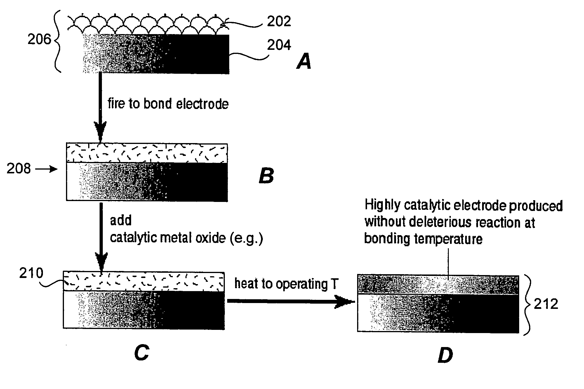
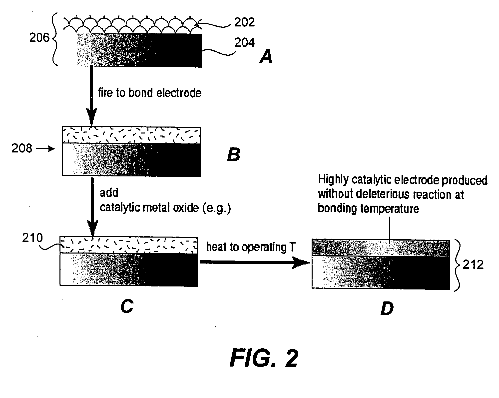
[0012] In one embodiment the present invention provides an electrode fabricated from highly electronically conductive materials such as metals, metal alloys, or electronically conductive ceramics. In this way, the electronic conductivity of the electrode substrate is maximized. Onto this electrode in the green state, a green ionic (e.g., electrolyte) film may be deposited and the assembly is co-fired at a temperature suitable to fully densify the film while the substrate retains porosity. In one embodiment a second green ionic (e.g., electrolyte) layer is deposited between the electrode and the assembly co-fired at a temperature to fully densify the film while the substrate and the second ionic layer retain porosity. Subsequently, a catalytic material is added to the electrode structure by infiltration of a metal salt and subsequent low temperature firing. The invention allows for an electrode with high electronic conductivity and sufficient catalytic activity to achieve high power density in an ionic (electrochemical) device such as fuel cells and electrolytic gas separation systems.

Problems solved by technology

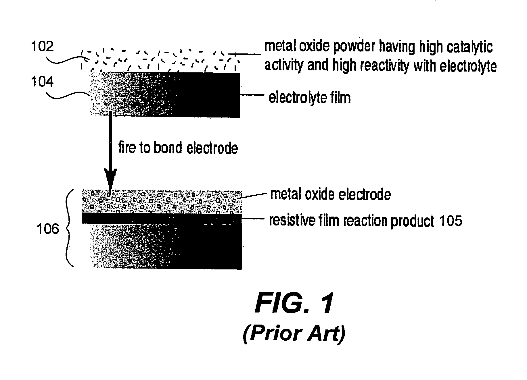
However, if such compounds were to be used with typical zirconia-based electrolytes, such as YSZ, a deleterious reaction in the temperature range of 1000-1400° C. typically needed to densify zirconia would be expected.
Similar problems may be encountered with sintering highly catalytic electrode materials on densified (fired) zirconia-base electrolytes since the sintering temperatures of about 1200° C. to 1400° C. are sufficient to cause the formation of a deleterious resistive film at the electrode / electrolyte interface.
However, this can hinder the performance of ionic devices, particularly at high current densities where ohmic drop due to current collection can lead to substantial efficiency losses.

Method used


Image

  • Solid state electrochemical composite
  • Solid state electrochemical composite
  • Solid state electrochemical composite

Examples


example

[0053] The following example illustrates aspects and features of a specific implementation in accordance with the present invention. It should be understood the following is representative only, and that the invention is not limited by the detail set forth in this example.

[0054] A composite structure in accordance with one embodiment of the present invention was prepared by the following proceedure. 40 vol % of 325 mesh, 410L stainless steel powder was mixed with 60 vol % polymer (acrylic plus polyethylene glycol (M.W. 6,000)). This was dried at ˜100 C to remove water, ground, and pressed into a 38 mm diameter disk approximately 2 mm thick. The disk was immersed in distilled water for 4 hours to remove the polyethylene glycol. The disk was fired to 900 C in an alumina tube furnace under flowing 4% H2 / He gas. The resulting disk was strong enough to handle. A paint consisting of polyethylene glycol, acrylic beads (as pore former), and 30 vol % of 8 mol % yttria stabilized zirconia po...


PUM

PropertyMeasurementUnit
thickaaaaaaaaaa
thickaaaaaaaaaa
thickaaaaaaaaaa

Abstract

Provided is a composite electrochemical device fabricated from highly electronically conductive materials such as metals, metal alloys, or electronically conductive ceramics. The electronic conductivity of the electrode substrate is maximized. The invention allows for an electrode with high electronic conductivity and sufficient catalytic activity to achieve high power density in ionic (electrochemical) devices such as fuel cells and electrolytic gas separation systems including oxygen generation system.

Description

CROSS-REFERENCE TO RELATED APPLICATIONS [0001] This application is a continuation-in-part and claims priority from U.S. Ser. No. 10 / 724,558, filed Nov. 26, 2003 which is divisional of U.S. Ser. No. 09 / 626,022, filed Jul. 27, 2000, now U.S. Pat. No. 6,682,482, which claims priority from U.S. Provisional Application No. 60 / 146,767, entitled SURFACE ADDITIVES FOR ENHANCED ELECTRODE PERFORMANCE, filed Jul. 31, 1999, the disclosures of which are all herein incorporated by reference for all purposes.STATEMENT OF GOVERNMENT SUPPORT [0002] This invention was made with government support in the course of or under prime contract No. DE-ACO3-76SF00098 between the U.S. Department of Energy and the University of California. The government has certain rights in this invention.BACKGROUND OF THE INVENTION [0003] The present invention relates generally to the field of electrochemical devices, and more particularly solid state electrochemical devices composed of one or more electrodes in contact with...

Claims


Application Information

Patent Timeline
Patent Type & Authority Applications(United States)
IPC IPC(8): C01B13/02H01M4/86H01M4/90H01M8/02H01M8/10H01M8/12
CPCC01B13/0255H01M4/90H01M4/9016H01M4/9025H01M8/0232H01M8/0236Y02E60/525H01M8/0618H01M8/1213H01M8/122H01M8/1246H01M8/1253Y02E60/521H01M8/0245Y02E60/50Y02P70/50
Inventor VISCO, STEVEN J.JACOBSON, CRAIG P.DEJONGHE, LUTGARD C.
Owner RGT UNIV OF CALIFORNIA
Why Eureka
Try Eureka